
 LOGIN
LOGIN Downloads


The Components options are categorized into 3 groups:
- Surface Mount
- Through-hole
- FP Designer
1. SURFACE MOUNT
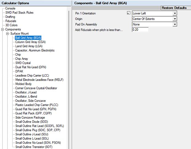
The Components options allow you to change the default settings for:
Pin 1 Orientation
- The default setting is Pin 1 Lower Left per IEC 61188-7 Standard.
- Use dropdown menu to change the Pin 1 orientation.
Origin
- The default setting is "Center of Extents" (or the center of gravity for pick & place).
- Use dropdown menu to change the footprint origin to Pin 1.
Pad On Assembly
- The default is "None" but the other options are "Outline" and "Filled".
- The default setting is "None" because additional outlines to every pad in a footprint increases file size, but you can change this to enhance the Assembly drawing.
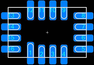
Default D-Shaped Lead Pad Shape
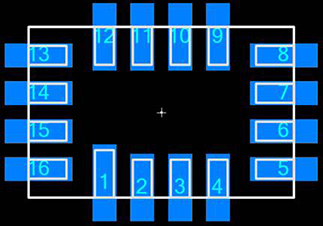
Default Rectangular Lead Pad Shape
- This is primarily used for QFN component families and the Terminal Lead Shape.
D-Shaped Terminal Leads have a unique setting for the pad shape:
Rectangle Terminal Leads have a unique setting for the pad shape:
Pin 1 Pad Shape
- This feature is rarely used, but its intention is to make Pin 1 a different pad shape.
- This is often used when silkscreen polarity marking cannot be used due to high density.
Add Local Fiducials when the pin pitch is less than any value you insert into Options.
- This feature was added a long time ago when fiducials were required by assembly for fine pitch packages like BGA and QFP.
- However, with the advances in component placement accuracy, fiducials are no longer required for most assembly shops.
2. THROUGH-HOLE
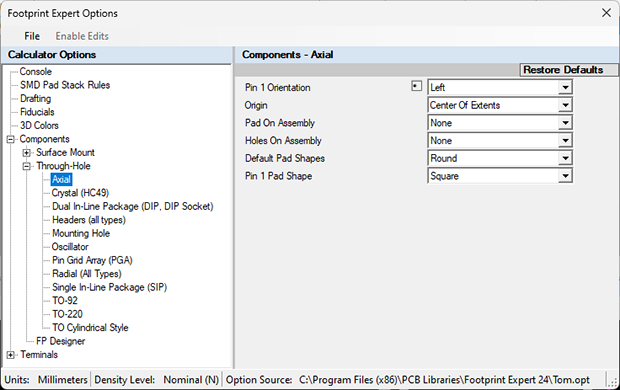
The Components options allow you to change the default settings for:
1 Orientation
- The default setting is Pin 1 Lower Left per IEC 61188-7 Standard.
- Use dropdown menu to change the Pin 1 orientation.
Origin
- The default setting is "Center of Extents" (or the center of gravity for pick & place).
- Use dropdown menu to change the footprint origin to Pin 1.
Pad On Assembly
- The default is "None"; other options are "Outline" and "Filled".
- The default setting is "None" because additional outlines to every pad in a footprint increases file size, but you can change this to enhance the Assembly drawing.
Hole On Assembly
Default Pad Shape
- Round is the default setting.
- Square and Rounded Square are optional.
Pin 1 Pad Shape
- Square is the default setting.
- Round and Rounded Square are optional.
3. FP DESIGNER
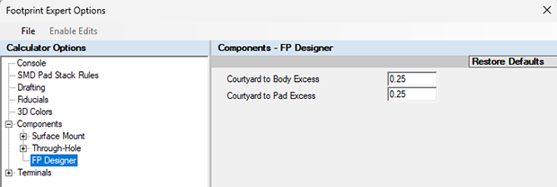
FP Designer (non-standard packages)
- The Courtyard to Body Excess default setting is 0.25.
- The Courtyard to Pad Excess default setting is 0.25.
