LOGIN
LOGIN Downloads


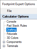
1. File > Options > Select Drafting
2. Legend Outlines and Text
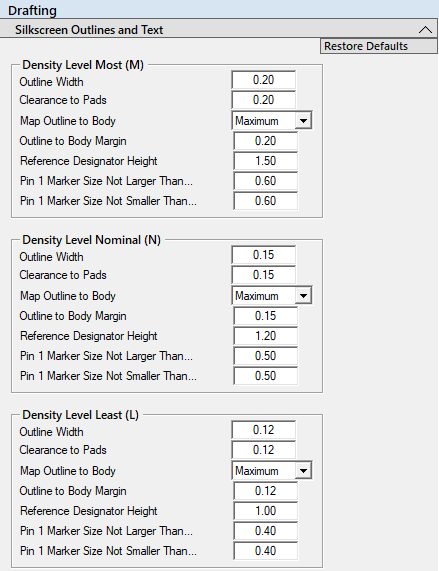
3. Density Levels - Most, Nominal and Least
Because the Silkscreen legend is included in the Gerber output, it can have different rules for each Density Level.
The following rules can be applied separately to each Density Level. It is important to note that most fabrication shops' minimum legend line width is 0.10 (4 mil).
a. Outline Width (default settings)
- Most Density default width is set to 0.15
- Nominal Density default width is set to 0.12
- Least Density default width is set to 0.10
- Note: if you make the silkscreen legend too thick, it will push the Courtyard out, consume more PCB space, and limit part placement. We recommend 0.20 for the thickest legend line width, 0.10 for the thinnest, and 0.15 for the average.
b. Clearance to Pads
- This is normally set to the same value as the default Line Width
- Note: The line width and legend to pad gap could be the same value, but you could also use a 0.20 line with a 0.15 Gap or a 0.15 line width with a 0.12 gap. You drive the Option Rules.
c. Map Outline Body
- None
- Maximum - default setting
(legend outline will map to the maximum package dimensions) - Nominal
- Minimum
- Margin
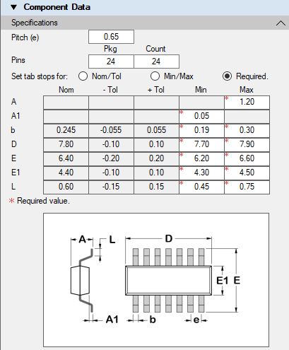
- This image of a calculator input shows the Nominal, Minimum and Maximum package dimensions.
d. Reference Designator Height
- Most Density default height is set to 1.50
- Nominal Density default height is set to 1.20
- Least Density default height is set to 1.00
e. Pin 1 Marker Size Not Larger Than...
- The default settings are:
- 0.60 - Density Level Most (M)
- 0.50 - Density Level Nominal (N)
- 0.40 - Density Level Least (L)
f. Pin 1 Marker Size Not Smaller Than...
- The default settings are:
- 0.60 - Density Level Most (M)
- 0.50 - Density Level Nominal (N)
- 0.40 - Density Level Least (L) - You can enter different values for the "Not Larger Than" and "Not Smaller Than"; the program will auto-size the dot per the pad width.
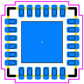
- Note: normally, a pin 1 polarity dot diameter is 0.40 minimum for clear visibility on the PCB for Post Assembly Inspection. Here is an example of a 0.65 mm pitch SOP with a 0.50 Pin 1 Dot.
4. All Density Levels
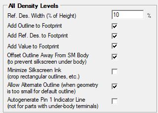
a. Ref. Des. Width (% of Height)
- This feature is only used for the CAD tool "Stroke" font. It is not used for Windows text fonts.
b. Add Outline to Footprint (on-off)
- The default is on, but some companies do not put silkscreen legend on final PCBs. This feature lets you easily build an entire PCB library with legend and one without.
c. Add Ref. Des. to Footprint (on/off)
- The default is On as most companies require a reference designator on the PCB to help locate components.
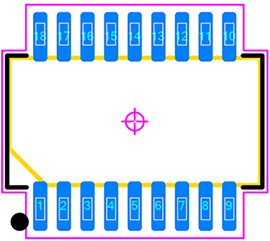
d. Offset Outline Away From SM Body
- The default is On and this is the result.
e. Minimize Silkscreen Ink (crop rectangle Outlines)
- Unchecked equals a Full Silkscreen outline
- Checked equals a Hatched Silkscreen outline
f. Allow Alternate Outline (when geometry is too small for default outline)
- Unchecked equals no silkscreen outline if the footprint is to small
- Checked equals a wraparound silkscreen outline if the footprint is to small
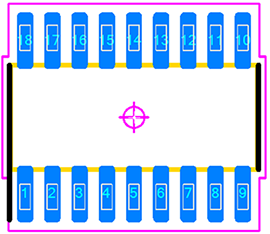
g. Autogenerate Pin 1 Indicator Line
- This feature draws a legend line next to Pin 1. Many designers use this instead of the pin 1 dot as it is located inside the placement courtyard. Note: this feature is only applicable for external terminal leads and not used for BTC (Bottom Termination Components) like Grid Array's or QFN, SON, DFN packages.
- Here is an example of a 0.65 mm pitch SOP with a Pin 1 Indicator Line:
5. Assembly Outlines and Text
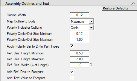
a. Outline Width
- Default value is set to 0.12, but you can change this value for your own custom library.
b. Map Outline Body
- Maximum - is the default setting; legend outline will map to the maximum package dimensions
- Nominal
- Minimum
c. Polarity Indicator Options
- None
- Chamfer - is the default setting
- Dot
- Circle - is the default setting
d. Polarity Dot and Circle Size Minimum
- Intended for small packages
- The Min/Max is a range that the calculator uses to scale the Dot Size per the package width
e. Polarity Dot and Circle Size Maximum
- Intended for large packages
f. Apply Polarity Bar to 2 Pin Part Types
- This is an on/off switch. On = Bar Polarity and Off (unchecked) = other polarity options
g. Ref. Des. Height Minimum
- Footprint Expert auto-adjusts the ref. des. height to fit in the middle of the assembly outline.
h. Ref. Des. Height Maximum
- The default value is 2.00.
i. Ref. Des. Width (% of Height)
- This feature is only used for the CAD tool "Stroke" font. It is not used for Windows text fonts.
j. Add Outline to Footprint (on/off)
- This feature allows you to turn Assembly Outline on or off; the default setting is On.
k. Add Ref. Des. to Footprint
- This feature allows you to turn Assembly Ref. Des. on or off; the default setting is On.
l. Add Polarity Indicators to Footprint
- This feature adds a polarity chamfer in the outline to the corner where Pin 1 is located.
6. Courtyard Outlines
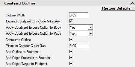
a. Outline Width
- The default value is 0.05.
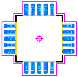
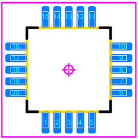
b. Contoured Courtyard (on/off)
- This feature selection is contoured outlines (on) or rectangular outlines (off)
- Contoured On:
- Contoured Off:
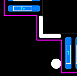
c. Minimum Courtyard Cut-in Gap
- The default value is 5.00. This feature allows the courtyard outline to cut in-between pads of whatever value you set. If the cut-in gap is 1.00 then the courtyard will contour between pads that have greater than 1.00 separation.
- Cut-in Gap 5.00.
- Cut-in Gap 0.50. The courtyard cut-in between pins 1 & 2.
d. Add Outline to Footprint (on/off)
- This feature turns the courtyard outline on or off; the default setting in On.
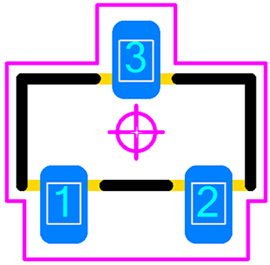
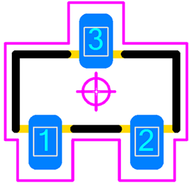
e. Add Origin Crosshair to Footprint (on/off)
- This feature turns the centroid crosshair outline on or off; the default setting in On.
f. Add Origin Target to Footprint (on/off)
- This feature turns the centroid circle outline on or off; the default setting in On.
g. Expand Courtyard to Include Legend (on/off)
- This feature bends the courtyard outside the silkscreen legend; the default setting is On.
h. Apply Courtyard Excess Option to Body (Yes/No)
- This feature applies the Courtyard Excess to Body or turns it off.
i. Expand Courtyard Excess Option to Pads (Yes/No/Ignore)
- This feature applies the Courtyard Excess to Pads, turns it off, or Ignores pads.
7. Component and Terminal Outlines
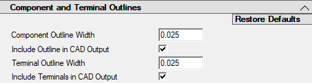
a. Component Outline Width
8. This feature sets the line width for the component package outline line width. The default value is 0.025 (1 mil).
a. Include Comp. Outline in CAD Output
9. This feature includes the component package outline in the library part on a mechanical layer. The default setting is On.
a. Terminal Outline Width
10. This feature sets the line width for the terminal lead outline line width. The default value is 0.025 (1 mil).
a. Include Terminals in CAD Output
11. This feature includes the terminal lead outline in the CAD library part on a mechanical layer. The
default setting is On. Including Terminals in the CAD output will place those
outlines on a mechanical layer.