
 LOGIN
LOGIN Downloads


There are 74 component family calculators that autogenerate 3D models from the package dimensions entered in the standard Surface Mount and Through-hole component families, as acknowledged in the IPC-7352 guideline.
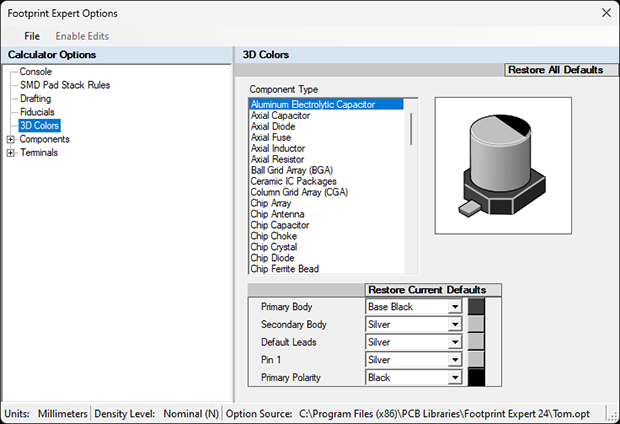
The default 3D colors for each component family are based on the common colors of each package. However, you can change the default colors to whatever you want. These colors will appear when you create a new footprint.
The basic 3D color assignments are:
- Primary Body
- Secondary Body
- Default Leads
- Pin 1
- Primary Polarity (for polarized packages)
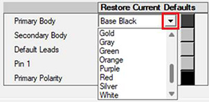
To change the default color, select the dropdown button in the color cell and a list of basic colors will be displayed.
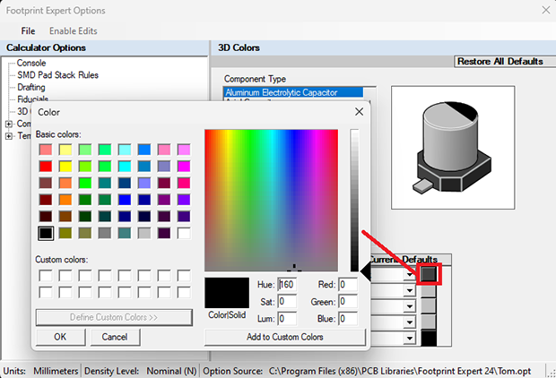
The color square to the right of the color name lets you select a Basic Color, or define Custom Colors.
When a new footprint is created, you can change the default color in the Calculator > 3D Colors panel.
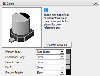
The updated color assignments made in the calculator are saved to the FPX file.
You can have multiple footprints with the same package dimensions but different color assignments, just manually edit the footprint name to specify the desired. Usually, the color names are abbreviated to 3 characters.
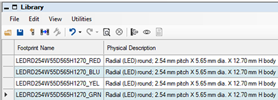
For example, if you have a series of LEDs with identical package dimensions but different color lights:
- Create an LED footprint with one specific color and save to your FPX file
- Manually update the footprint name with desired color
- Repeat process until the series of LED indicators is completed
To batch build the entire group of LEDs:
- Ctrl-A or Ctrl-Click each LED to highlight them
- Right-click
- Click "Build Selection"
