

|
|
Missing Tolerances |
Post Reply 
|
| Author | |
5not4 
Active User 
Joined: 09 Jul 2013 Status: Offline Points: 40 |
 Post Options Post Options
") Thanks(0) Thanks(0)
 Quote Reply Quote Reply
 Topic: Missing Tolerances Topic: Missing TolerancesPosted: 18 Feb 2015 at 9:07am |
|
Is there a 'typical' tolerance to be used when there is no value given on a datasheet?
For example - I need to make a footprint for OSCCC style crystal but no dimension is given for the D1 / E1 values (gap between the feet). Nominal values are provided for foot width (X and Y) so the gap between can be calculated easily. What tolerance should be used for an accurate footprint? Any and all comments welcome and greatly appreciated. Datasheet example 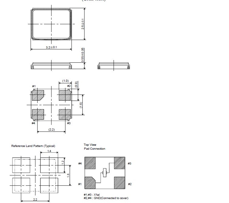 |
|
 |
|

|
|
|
|
|
Tom H
Admin Group 

Joined: 05 Jan 2012 Location: San Diego, CA Status: Offline Points: 6074 |
Post Options
Thanks(0)
Quote Reply
Posted: 18 Feb 2015 at 9:52am |
|
Tolerances are normally +/- 0.20 mm for larger dimensions and between +/- 0.10 & 0.15 mm for small dimensions.
|
|
|
|
|
5not4
Active User
Joined: 09 Jul 2013 Status: Offline Points: 40 |
Post Options
Thanks(0)
Quote Reply
Posted: 18 Feb 2015 at 10:31am |
|
Good information, Tom!
Thanks for the quick response. Roy.
|
|
|
|
|
Post Reply
|
|
| Tweet |
| Forum Jump | Forum Permissions You cannot post new topics in this forum You cannot reply to topics in this forum You cannot delete your posts in this forum You cannot edit your posts in this forum You cannot create polls in this forum You cannot vote in polls in this forum |


 Topic Options