Missing Tolerances
Printed From: PCB Libraries Forum
Category: Libraries
Forum Name: Footprints / Land Patterns
Forum Description: [General or a CAD specific issues / discussions]
URL: https://www.PCBLibraries.com/forum/forum_posts.asp?TID=1561
Printed Date: 26 Jun 2026 at 9:55am
Topic: Missing Tolerances
Posted By: 5not4
Subject: Missing Tolerances
Date Posted: 18 Feb 2015 at 9:07am
|
Is there a 'typical' tolerance to be used when there is no value given on a datasheet? For example - I need to make a footprint for OSCCC style crystal but no dimension is given for the D1 / E1 values (gap between the feet). Nominal values are provided for foot width (X and Y) so the gap between can be calculated easily. What tolerance should be used for an accurate footprint? Any and all comments welcome and greatly appreciated. Datasheet example 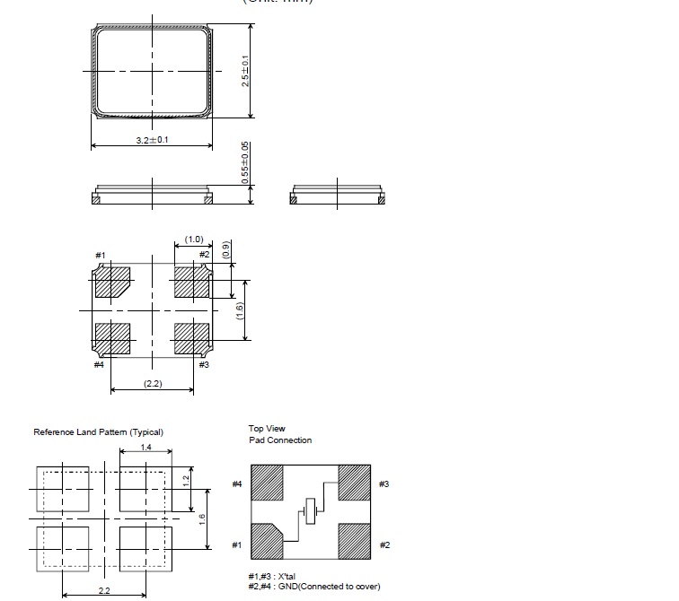 |
Replies:
Posted By: Tom H
Date Posted: 18 Feb 2015 at 9:52am
|
Tolerances are normally +/- 0.20 mm for larger dimensions and between +/- 0.10 & 0.15 mm for small dimensions. ------------- Stay connected - follow us! https://twitter.com/PCBLibraries" rel="nofollow - X - http://www.linkedin.com/company/pcb-libraries-inc-/" rel="nofollow - LinkedIn |
Posted By: 5not4
Date Posted: 18 Feb 2015 at 10:31am
|
Good information, Tom! Thanks for the quick response. Roy.
|