

|
|
Axial Components Pitch Calculation |
Post Reply 
|
Page 12> |
| Author | |
prathibha 
New User 
Joined: 24 May 2016 Status: Offline Points: 18 |
 Post Options Post Options
") Thanks(2) Thanks(2)
 Quote Reply Quote Reply
 Topic: Axial Components Pitch Calculation Topic: Axial Components Pitch CalculationPosted: 26 May 2016 at 1:33am |
|
Hi all, Can anyone please tel me how to calculate pitch for Axial Components like resistor, Diode, etc. Thanks |
|
 |
|

|
|
|
|
|
mahmoodv99
Advanced User 
Joined: 16 Jan 2016 Status: Offline Points: 93 |
Post Options
Thanks(2)
Quote Reply
Posted: 26 May 2016 at 2:39am |
|
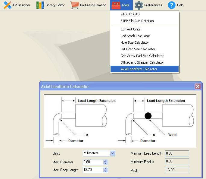
You can use Axial Lead form calculator from Tools
  |
|
|
|
|
prathibha
New User
Joined: 24 May 2016 Status: Offline Points: 18 |
Post Options
Thanks(1)
Quote Reply
Posted: 26 May 2016 at 3:16am |
|
Thanks...
Is there any theoretical formula available in field to calculate pitch for Axial Components. |
|
|
|
|
Tom H
Admin Group 

Joined: 05 Jan 2012 Location: San Diego, CA Status: Offline Points: 6088 |
Post Options
Thanks(1)
Quote Reply
Posted: 26 May 2016 at 6:01am |
|
Eventually the Axial Lead Pitch will be incorporated into the Calculator. However, our programmers are very busy right now adding Schematic Symbol automation and enhancing the mathematical model for SMD pad size calculations for micro-miniature packages. The Axial Lead math formula comes from IPC-2221 or IPC-2222. |
|
|
|
|
Dale
Active User 
Joined: 04 Mar 2012 Location: Australia Status: Offline Points: 15 |
Post Options
Thanks(1)
Quote Reply
Posted: 26 May 2016 at 8:14pm |
|
The maximum pitch is controlled by the available lead length.
The minimum pitch is set by (a) the maximum body dimension - don't forget to consider all sources if you are multi-sourcing (b) the positional error of the part on the tape (c) the requirements of the lead forming machine. Note that the leads must NEVER be bent by holding the body. They are always bent by clamping the lead and applying the bend on the non-body side of the clamp. The width of the clamp is set by the machine design, which in turn is affected by the diameter of the lead requiring bending. e.g. A 1.0mm dia lead requires a much bigger clamp than a 0.5mm lead dia. Once those issues are considered, the lead pitch becomes your choice. |
|
|
|
|
EldenNelson
New User
Joined: 16 Jun 2016 Status: Offline Points: 1 |
Post Options
Thanks(0)
Quote Reply
Posted: 16 Jun 2016 at 10:15am |
|
Hi...actually the component size is standard there in the libraries of the PCB designing. But still if you want to calculate the pitch then you can use the internal tools available in the package itself. Choose the "Tools" icon from the Main Toolbar and then select the Axial Lead Form Calculator. |
|
|
|
|
SWB01
Active User
Joined: 24 Mar 2013 Status: Offline Points: 40 |
Post Options
Thanks(0)
Quote Reply
Posted: 03 Nov 2020 at 12:13am |
Is this accurate? I do not have access to the latest revisions of either of these standards, so maybe it was updated. In the version I have, the calculation for the lead length extension is specified as "straight for 1 diameter/lead thickness, but not less than 0.8 mm [0.031 in]." Library Expert calculates a value much larger than this for the lead length extension. For example, for a lead diameter of 0.8 mm, Library Expert calculates a lead length extension of 2.40 mm – three times the value suggested by my copy of the standard.
|
|
|
|
|
Ian S
Committee 
Joined: 21 Aug 2014 Status: Offline Points: 67 |
Post Options
Thanks(0)
Quote Reply
Posted: 03 Nov 2020 at 2:27am |
|
2.4 mm is correct for a 0.8 mm dia lead with a standard bend form (as opposed to a welded bend) component, per IPC.
To calculate the lead bend extension from the end of the part, you need to add the other parts of the calculation which are the value of the minimum bend radius (R), plus the radius of the lead. Per IPC-2221A: The Minimum Radius (R) is dependant upon the maximum component lead diameter where: R = 1 for max lead diameter up to 0.8 mm R = 1.5 for max lead diameter 0.8 mm to 1.2 mm R = 2 for max lead diameter larger than 1.2 mm |
|
|
|
|
Ian S
Committee
Joined: 21 Aug 2014 Status: Offline Points: 67 |
Post Options
Thanks(0)
Quote Reply
Posted: 03 Nov 2020 at 2:42am |
|
Should clarify that R is a variable as I missed a key word from the R calculation (sorry!).
Correction below:
R = 1 diameter (for max lead diameter up to 0.8 mm) R = 1.5 diameters (for max lead diameter 0.8 mm to 1.2 mm) R = 2 diameters (for max lead diameter larger than 1.2 mm) |
|
|
|
|
SWB01
Active User
Joined: 24 Mar 2013 Status: Offline Points: 40 |
Post Options
Thanks(1)
Quote Reply
Posted: 03 Nov 2020 at 10:29am |
For the total pitch, yes. But (at least according to the revision I'm looking at, as well as the diagram in Library Expert's Axial Leadform Calculator) the lead length extension (L) is from the end of the part (or weld bead) to the beginning of the bend. This value does not include the bend radius or lead radius. Those are added to L to determine the pitch. So, in math, my reading of the IPC calculation is: b : lead diameter D : part length, including weld beads if any L : lead length extension R : bend radius m : bend radius multiplier, according to the table in Ian's message e : pitch L = max( 0.8, b ) R = m b e = D + 2 ( L + R + b / 2 )
|
|
|
|
|
Post Reply
|
Page 12> |
| Tweet |
| Forum Jump | Forum Permissions You cannot post new topics in this forum You cannot reply to topics in this forum You cannot delete your posts in this forum You cannot edit your posts in this forum You cannot create polls in this forum You cannot vote in polls in this forum |


 Topic Options
 Tom H wrote: