Axial Components Pitch Calculation
Printed From: PCB Libraries Forum
Category: PCB Footprint Expert
Forum Name: Questions & Answers
Forum Description: issues and technical support
URL: https://www.PCBLibraries.com/forum/forum_posts.asp?TID=1896
Printed Date: 24 Jul 2026 at 1:28pm
Topic: Axial Components Pitch Calculation
Posted By: prathibha
Subject: Axial Components Pitch Calculation
Date Posted: 26 May 2016 at 1:33am
|
Hi all, Can anyone please tel me how to calculate pitch for Axial Components like resistor, Diode, etc. Thanks |
Replies:
Posted By: mahmoodv99
Date Posted: 26 May 2016 at 2:39am
You can use Axial Lead form calculator from Tools  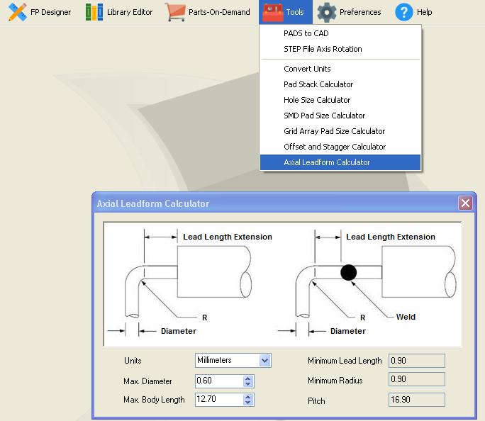 |
Posted By: prathibha
Date Posted: 26 May 2016 at 3:16am
|
Thanks... Is there any theoretical formula available in field to calculate pitch for Axial Components. |
Posted By: Tom H
Date Posted: 26 May 2016 at 6:01am
|
Eventually the Axial Lead Pitch will be incorporated into the Calculator. However, our programmers are very busy right now adding Schematic Symbol automation and enhancing the mathematical model for SMD pad size calculations for micro-miniature packages. The Axial Lead math formula comes from IPC-2221 or IPC-2222. ------------- Stay connected - follow us! https://twitter.com/PCBLibraries" rel="nofollow - X - http://www.linkedin.com/company/pcb-libraries-inc-/" rel="nofollow - LinkedIn |
Posted By: Dale
Date Posted: 26 May 2016 at 8:14pm
|
The maximum pitch is controlled by the available lead length. The minimum pitch is set by (a) the maximum body dimension - don't forget to consider all sources if you are multi-sourcing (b) the positional error of the part on the tape (c) the requirements of the lead forming machine. Note that the leads must NEVER be bent by holding the body. They are always bent by clamping the lead and applying the bend on the non-body side of the clamp. The width of the clamp is set by the machine design, which in turn is affected by the diameter of the lead requiring bending. e.g. A 1.0mm dia lead requires a much bigger clamp than a 0.5mm lead dia. Once those issues are considered, the lead pitch becomes your choice. |
Posted By: EldenNelson
Date Posted: 16 Jun 2016 at 10:15am
|
Hi...actually the component size is standard there in the libraries of the PCB designing. But still if you want to calculate the pitch then you can use the internal tools available in the package itself. Choose the "Tools" icon from the Main Toolbar and then select the Axial Lead Form Calculator. http://www.7pcb.ca/PCB-Assembly-services/" rel="nofollow - printed circuits assembly
|
Posted By: SWB01
Date Posted: 03 Nov 2020 at 12:13am
Is this accurate? I do not have access to the latest revisions of either of these standards, so maybe it was updated. In the version I have, the calculation for the lead length extension is specified as "straight for 1 diameter/lead thickness, but not less than 0.8 mm [0.031 in]." Library Expert calculates a value much larger than this for the lead length extension. For example, for a lead diameter of 0.8 mm, Library Expert calculates a lead length extension of 2.40 mm – three times the value suggested by my copy of the standard.
|
 Tom H wrote:
Posted By: Ian S
Date Posted: 03 Nov 2020 at 2:27am
|
2.4 mm is correct for a 0.8 mm dia lead with a standard bend form (as opposed to a welded bend) component, per IPC. To calculate the lead bend extension from the end of the part, you need to add the other parts of the calculation which are the value of the minimum bend radius (R), plus the radius of the lead. Per IPC-2221A: The Minimum Radius (R) is dependant upon the maximum component lead diameter where: R = 1 for max lead diameter up to 0.8 mm R = 1.5 for max lead diameter 0.8 mm to 1.2 mm R = 2 for max lead diameter larger than 1.2 mm |
Posted By: Ian S
Date Posted: 03 Nov 2020 at 2:42am
|
Should clarify that R is a variable as I missed a key word from the R calculation (sorry!). Correction below:
R = 1 diameter (for max lead diameter up to 0.8 mm) R = 1.5 diameters (for max lead diameter 0.8 mm to 1.2 mm) R = 2 diameters (for max lead diameter larger than 1.2 mm) |
Posted By: SWB01
Date Posted: 03 Nov 2020 at 10:29am
For the total pitch, yes. But (at least according to the revision I'm looking at, as well as the diagram in Library Expert's Axial Leadform Calculator) the lead length extension (L) is from the end of the part (or weld bead) to the beginning of the bend. This value does not include the bend radius or lead radius. Those are added to L to determine the pitch. So, in math, my reading of the IPC calculation is: b : lead diameter D : part length, including weld beads if any L : lead length extension R : bend radius m : bend radius multiplier, according to the table in Ian's message e : pitch L = max( 0.8, b ) R = m b e = D + 2 ( L + R + b / 2 )
|
Posted By: Jeff.M
Date Posted: 04 Nov 2020 at 11:13am
|
Ian's solution is correct: e = D + 2 ( L + R + b / 2 ) I write it : e = D + 2 ( L + R ) + b Where: b : lead diameter D : part length, including weld beads if any L : lead length extension R : bend radius m : bend radius multiplier, according to the table in Ian's
message e : pitch ------------- Stay connected - follow us! https://twitter.com/PCBLibraries" rel="nofollow - X - http://www.linkedin.com/company/pcb-libraries-inc-/" rel="nofollow - LinkedIn |
Posted By: SWB01
Date Posted: 04 Nov 2020 at 12:15pm
(Note that the calculation described by Ian S does not match this equation.) If this is the correct formula, then Library Expert is wrong, since this is not the math that the Axial Leadform Calculator is using. Example with b=0.5 and D=10:Pitch according to this formula = 13.1; Pitch according to the Axial Leadform Calculator = 14.0. Example with b=0.85 and D=7.6:Pitch according to this formula = 12.7; Pitch according to the Axial Leadform Calculator = 16.1.
|
Posted By: Ian S
Date Posted: 04 Nov 2020 at 12:57pm
|
SWB01 - I agree that PCB Libraries tool's axial component calculation for pin pitch is too large and does not match the calculation per IPC-2221A. I also agree that the SWB01 and Jeff's calculations are as expected. PS. SWB01, in your original post you questioned why the tool came up with a figure of 2.4 mm, as opposed to 0.8 mm, for the 'lead length extension' for a lead diameter of 0.8 mm - I think you misunderstood my reply as I was demonstrating that the calculated 2.4 mm figure was referring to the distance from the component body to the centre of the drill hole and not the straight part of the lead (which the standard clearly defines as "Straight for 1 diameter, but not less than 0.8 mm"). Ian
|
Posted By: SWB01
Date Posted: 04 Nov 2020 at 12:59pm
|
Ian S: Got it. Yes, I indeed misunderstood your reply. |
Posted By: Jeff.M
Date Posted: 05 Nov 2020 at 12:27pm
|
Looks like the formula changed from: Old formula had Lead Length calculated as 1.5 diameters for least (< 0.8mm); 2.5 diameters for nominal (0.8<1.2) and 3.5 for most (1.2<). Current has just one diameter for each lead length (not less than 0.8) and produces the following sample results. e = D + 2 ( L + r ) + b ------------- Stay connected - follow us! https://twitter.com/PCBLibraries" rel="nofollow - X - http://www.linkedin.com/company/pcb-libraries-inc-/" rel="nofollow - LinkedIn |
Posted By: Tom H
Date Posted: 05 Nov 2020 at 12:30pm
|
Note: this feature update will be in the V2020.03 release this weekend. ------------- Stay connected - follow us! https://twitter.com/PCBLibraries" rel="nofollow - X - http://www.linkedin.com/company/pcb-libraries-inc-/" rel="nofollow - LinkedIn |
Posted By: SWB01
Date Posted: 05 Nov 2020 at 8:54pm
Great! Thank you!
|
Posted By: Tom H
Date Posted: 16 Nov 2020 at 9:21am
|
V2020.03 is officially released with this Axial Lead Bend formula fixed. http://www.pcblibraries.com/downloads " rel="nofollow - www.pcblibraries.com/downloads ------------- Stay connected - follow us! https://twitter.com/PCBLibraries" rel="nofollow - X - http://www.linkedin.com/company/pcb-libraries-inc-/" rel="nofollow - LinkedIn |