|
|
Pin 1 Dot on Pads |
Post Reply 
|
| Author | |
GrungyRemnant 
Advanced User 
Joined: 17 Oct 2013 Status: Offline Points: 91 |
 Post Options Post Options
") Thanks(0) Thanks(0)
 Quote Reply Quote Reply
 Topic: Pin 1 Dot on Pads Topic: Pin 1 Dot on PadsPosted: 22 Sep 2016 at 7:08am |
|
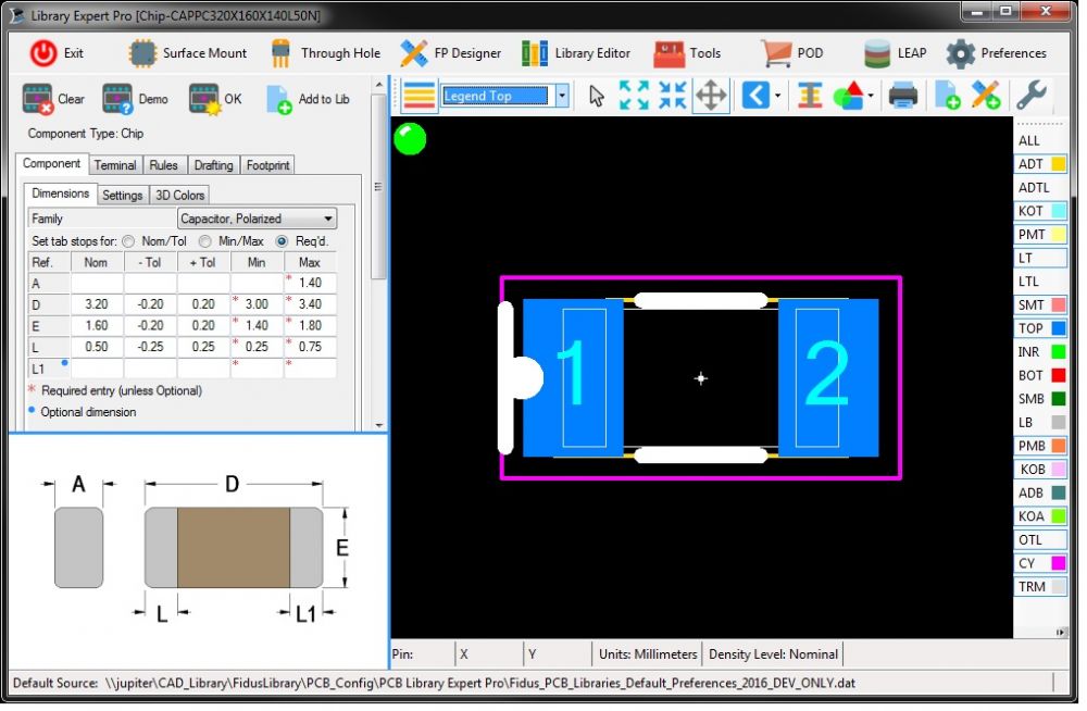
It seems there are Pin 1 dot issues on 2 pin polarized
parts. The pin 1 dot is on the pad. I’ve noticed it with the following families:
CHIP – Polarized MELF Molded Body SODFL Is there a preference setting causing this? I don’t see any control over the position in the preferences besides Legend Outline Placement Roundoff. But I don’t want to change that value as it changes all the Silk lines as well as the pin 1 dot. It is currently set to 0.01 which is the default I believe. This problem is present in version 2016.10 and 2016.11 Can this be corrected with a setting change or is it a bug? See image below of a demo polarized chip cap. Regards, Chris
|
|
 |
|
|
|
|
Tom H
Admin Group 

Joined: 05 Jan 2012 Location: San Diego, CA Status: Offline Points: 5716 |
Post Options
Thanks(0)
Quote Reply
Posted: 23 Sep 2016 at 8:30am |
|
This issue has been fixed in the latest V2016.11 pre-release - www.pcblibraries.com/downloads Let us know if you have any further issues and thank you for reporting this issue. |
|
|
|
|
Post Reply
|
|
| Tweet |
| Forum Jump | Forum Permissions You cannot post new topics in this forum You cannot reply to topics in this forum You cannot delete your posts in this forum You cannot edit your posts in this forum You cannot create polls in this forum You cannot vote in polls in this forum |


 Topic Options