Pin 1 Dot on Pads
Printed From: PCB Libraries Forum
Category: PCB Footprint Expert
Forum Name: Questions & Answers
Forum Description: issues and technical support
URL: https://www.PCBLibraries.com/forum/forum_posts.asp?TID=1966
Printed Date: 25 Jul 2026 at 9:20am
Topic: Pin 1 Dot on Pads
Posted By: GrungyRemnant
Subject: Pin 1 Dot on Pads
Date Posted: 22 Sep 2016 at 7:08am
|
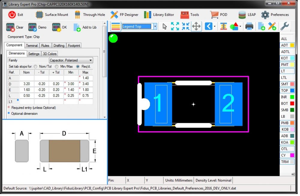
It seems there are Pin 1 dot issues on 2 pin polarized
parts. The pin 1 dot is on the pad. I’ve noticed it with the following families:
CHIP – Polarized MELF Molded Body SODFL Is there a preference setting causing this? I don’t see any control over the position in the preferences besides Legend Outline Placement Roundoff. But I don’t want to change that value as it changes all the Silk lines as well as the pin 1 dot. It is currently set to 0.01 which is the default I believe. This problem is present in version 2016.10 and 2016.11 Can this be corrected with a setting change or is it a bug? See image below of a demo polarized chip cap. Regards, Chris
|
Replies:
Posted By: Tom H
Date Posted: 23 Sep 2016 at 8:30am
|
This issue has been fixed in the latest V2016.11 pre-release - http://www.pcblibraries.com/downloads" rel="nofollow - www.pcblibraries.com/downloads Let us know if you have any further issues and thank you for reporting this issue. ------------- Stay connected - follow us! https://twitter.com/PCBLibraries" rel="nofollow - X - http://www.linkedin.com/company/pcb-libraries-inc-/" rel="nofollow - LinkedIn |