
 |

|
3D STEP to VRML |
Post Reply 
|
Page 12> |
| Author | |
dwaltoneng 
Advanced User 
Joined: 02 Mar 2013 Location: Australia Status: Offline Points: 193 |
 Post Options Post Options
 Thanks(0) Thanks(0)
 Quote Quote  Reply Reply
 Topic: 3D STEP to VRML Topic: 3D STEP to VRMLPosted: 17 Jun 2013 at 2:27pm |
|
Has anyone any suggestions on converting 3D STEP to VRML? Or for simplifying the VRML file?
|
|
 |
|

|
|
 |
|
chrisa_pcb 
Moderator Group 
Joined: 29 Jul 2012 Location: San Diego Status: Offline Points: 772 |
 Post Options Post Options
 Thanks(0) Thanks(0)
 Quote Quote  Reply Reply
 Posted: 17 Jun 2013 at 5:29pm Posted: 17 Jun 2013 at 5:29pm |
|
Given that VRML is a markup language, the size is understandable. Right now we're focusing on getting all of the families(both surface mount and throughhole) to work and getting everything stable before even considering outputting to alternate formats. STEP 3D is the core as it seemed to provide the most compatibility across the board with the most number of programs, and actually ended up being fairly easy to work with once I understood and got the code setup for it.
. And it sounds from your comments like DipTrace has problems when the VRML file gets fairly large(and the generated STEP 3D files can get fairly large, especially the ones with filleted corners and what not). |
|
 |
|
jameshead 
Expert User 
Joined: 20 Mar 2012 Location: Oxfordshire, UK Status: Offline Points: 576 |
 Post Options Post Options
 Thanks(0) Thanks(0)
 Quote Quote  Reply Reply
 Posted: 18 Jun 2013 at 1:02am Posted: 18 Jun 2013 at 1:02am |
|
At the moment I either grab a 3D model from the manufacturers website or use FreeCAD to knock up something. I have been meaning to look at the STEP output from FPX but your comment "the generated STEP 3D files can get fairly large, especially the ones with filleted corners and what not" raises a red flag.
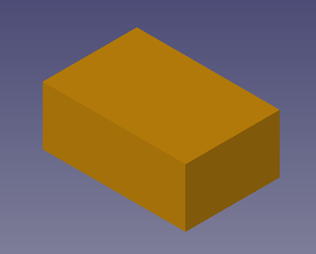
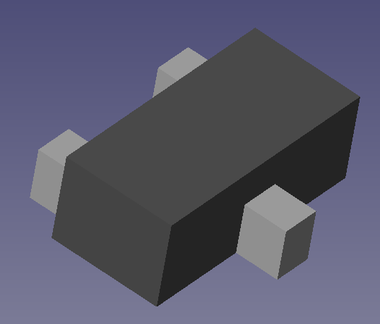
Pulsonix works with both IDF and STEP files. It works with STEP files by importing a STEP file for a PCB that has been output from an MCAD program, or exporting a STEP file of board and components. Pulsonix will either use an existing STEP file for a component or create one based on the component type and if you've specified anything in the Pulsonix 3D viewer. If you have an existing STEP model you can place it in a folder, then in the footprint in the Pulsonix library (or the part) place three attributes to point to the STEP file filename, X/Y/Z rotation, and X/Y/Z offset. The biggest hassle when dealing with STEP files downloaded from manufacturers is the X/Y/Z rotations and offsets which appear to be random and vary between parts, including parts from the same manufacturers. To be honest we found the more elaberate manufacturer-supplied STEP files and Pulsonix generated STEP models for components to be a hassle for our MCAD Engineers when they imported into Solidworks since Pulsonix was creating a fancy component body with bended legs and terminals on chip components. They've told me that this is a hassle for them to deal with, increasing complexity and file size unnecessarily. They are only interested in a simple space model - they don't want or need fancy chamfers on IC bodies that take up file space in the STEP file and when processing the models in Solidworks. With that in mind I began using FreeCAD recently to create some simple STEP models. All we need for a chip component is a single cube of the maximum size, whilst all we need for something like a SOP chip is a cube for the body and a couple of cubes for the two rows of legs, and for SOT-23s, a cube for the body and a cube for each leg. See these examples: Chip CAP:  SOT-23  SOP or SOIC  I've not got around to asking for a demo of the sTEP from FPX yet but if you're putting the jazzy bits in then I'd probably not be interested in it. A choice might be useful between a simple block STEP file or a whistles-and-bells STEP file. |
|
 |
|
Tom H 
Admin Group 

Joined: 05 Jan 2012 Location: San Diego, CA Status: Offline Points: 5989 |
 Post Options Post Options
 Thanks(0) Thanks(0)
 Quote Quote  Reply Reply
 Posted: 18 Jun 2013 at 7:07am Posted: 18 Jun 2013 at 7:07am |
|
Yes, large Pin Count BGA STEP files can be 35MB but the average 3D STEP file is less than 100KB each.
The 3D STEP files from the PCB Library Expert (LE) are High Quality and you create them with the same button you create Footprints. They have the same rotation, orign and name as the Footprint. And they're 100% customized for every Footprint. I think once you try the 3D STEP feature in LE you'll never use anything else. It's just too easy, especially with the "Parts on Demand" (POD) project that will have millions of component mfr. part numbers at your fingertips. |
|
 |
|
jameshead 
Expert User 
Joined: 20 Mar 2012 Location: Oxfordshire, UK Status: Offline Points: 576 |
 Post Options Post Options
 Thanks(0) Thanks(0)
 Quote Quote  Reply Reply
 Posted: 18 Jun 2013 at 7:40am Posted: 18 Jun 2013 at 7:40am |
|
It's the "High Quality" label that might be an issue. It's not me that needs to be persueded when it comes to STEP models from FPX - it's the Mechanical CAD Engineers here using Solidworks.
Here we have two of them (they're nice chaps really, even when they're making the PCB profiles smaller!). We use Solidworks and they are the ones that are saying that the elaborate STEP models with the modeled terminals are not suitable for what they want. They have to do extra work on them. I come from an Electronics background and have only just started to "play" with FreeCAD so I'm not totally familiar with how they are taking and using this data but the feedback they've been giving me is that the simple cube shapes are a lot easier and quicker for them to work with in Solidworks. |
|
 |
|
Tom H 
Admin Group 

Joined: 05 Jan 2012 Location: San Diego, CA Status: Offline Points: 5989 |
 Post Options Post Options
 Thanks(0) Thanks(0)
 Quote Quote  Reply Reply
 Posted: 18 Jun 2013 at 7:51am Posted: 18 Jun 2013 at 7:51am |
|
I use SolidWorks too.
Did you download our 3D STEP for the Component Familes supported in the PCB Library Expert? |
|
 |
|
jameshead 
Expert User 
Joined: 20 Mar 2012 Location: Oxfordshire, UK Status: Offline Points: 576 |
 Post Options Post Options
 Thanks(0) Thanks(0)
 Quote Quote  Reply Reply
 Posted: 18 Jun 2013 at 8:30am Posted: 18 Jun 2013 at 8:30am |
|
We've purchased the basic Pulsonix 2013 upgrade from 2012. Currently running 2013.04. All they are after is a simple space model to check for mechanical fit. They aren't interested in "nice" graphics, nor interested in the component legs being correct. |
|
 |
|
chrisa_pcb 
Moderator Group 
Joined: 29 Jul 2012 Location: San Diego Status: Offline Points: 772 |
 Post Options Post Options
 Thanks(0) Thanks(0)
 Quote Quote  Reply Reply
 Posted: 18 Jun 2013 at 9:44am Posted: 18 Jun 2013 at 9:44am |
|
I don't see any reason that we can't also provide a 'lower detail' model option as part of the generation process. This will not come online immediately, as i'm simply focused on getting the full set of families to come online, but there is no reason it can't be done. For something like a BGA, would you also want all the balls to simply be cylinders?
|
|
 |
|
Nick B 
Admin Group 

Joined: 02 Jan 2012 Status: Offline Points: 1976 |
 Post Options Post Options
 Thanks(0) Thanks(0)
 Quote Quote  Reply Reply
 Posted: 18 Jun 2013 at 10:13am Posted: 18 Jun 2013 at 10:13am |
|
This is exactly why we have intro pricing now - won't last for long.
|
|
 |
|
chrisa_pcb 
Moderator Group 
Joined: 29 Jul 2012 Location: San Diego Status: Offline Points: 772 |
 Post Options Post Options
 Thanks(0) Thanks(0)
 Quote Quote  Reply Reply
 Posted: 18 Jun 2013 at 12:28pm Posted: 18 Jun 2013 at 12:28pm |
|
I've played around with the BGA a bit and concerning the pins... balls(sphere) for the BGA are actually the most ideal way of doing this while keeping some definition. Changing them to squares is actually a lot more intensive and produces a file three times the size because it has to generate 6 faces for every pin, rather than 2 iirc.
Pretty much the next step lower would be to have a solid cube bound the extents of the pins, and at that point you wouldn't be able to tell if any pins were removed. But since you're simply using low quality for mechanical fit, this may or may not be ok as the area inside of a BGA that has no center pins could feasibly be used for part placement. I guess you could kick it up to high quality at that point if its an issue. |
|
 |
|
Post Reply 
|
Page 12> |
| Tweet |
| Forum Jump | Forum Permissions  You cannot post new topics in this forum You cannot reply to topics in this forum You cannot delete your posts in this forum You cannot edit your posts in this forum You cannot create polls in this forum You cannot vote in polls in this forum |