
 |

|
IPC-7351 Placement Tolerance Setting |
Post Reply 
|
| Author | |
drj-bbe 
Advanced User 
Joined: 08 Jul 2015 Status: Offline Points: 71 |
 Post Options Post Options
 Thanks(1) Thanks(1)
 Quote Quote  Reply Reply
 Topic: IPC-7351 Placement Tolerance Setting Topic: IPC-7351 Placement Tolerance SettingPosted: 15 Jul 2015 at 7:36pm |
|
Hello,
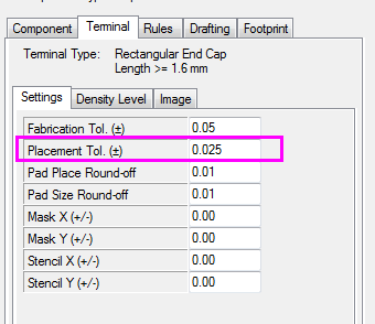
For placement tolerance below, it means tolerance for component placed by SMT pick&place machine, right? Why the default accuracy is so high 0.025mm? We used FUJI AIM machine which placement accuracy is 0.04mm.
 |
|
 |
|

|
|
 |
|
Tom H 
Admin Group 

Joined: 05 Jan 2012 Location: San Diego, CA Status: Offline Points: 6012 |
 Post Options Post Options
 Thanks(1) Thanks(1)
 Quote Quote  Reply Reply
 Posted: 16 Jul 2015 at 7:54am Posted: 16 Jul 2015 at 7:54am |
|
We (PCB Libraries, Inc.) and IPC agrees with you too.
We're working on the new IPC-7351C and we removed the manufacturing tolerances from the standard mathematical model. In our last committee meeting at IPC APEX is was voted to remove the manufacturing tolerances but we need to simulate the new math on a variety of components and compare the results. This update will be reflected in V2016 Library Expert after we run tests for the next few months. But it's OK for you to change the manufacturing tolerance in the current Library Expert. It's a User Definable setting. I would also make the fabrication tolerance 0 because every fabrication shop swells the outer layer etch to compensate for their etching process tolerance. There is no need for double tolerance.
|
|
 |
|
drj-bbe 
Advanced User 
Joined: 08 Jul 2015 Status: Offline Points: 71 |
 Post Options Post Options
 Thanks(0) Thanks(0)
 Quote Quote  Reply Reply
 Posted: 16 Jul 2015 at 6:18pm Posted: 16 Jul 2015 at 6:18pm |
|
Many thanks for your explanation. |
|
 |
|
dramos 
Advanced User 
Joined: 18 Feb 2021 Status: Offline Points: 88 |
 Post Options Post Options
 Thanks(0) Thanks(0)
 Quote Quote  Reply Reply
 Posted: 10 Feb 2023 at 2:06am Posted: 10 Feb 2023 at 2:06am |
|
Hi to all,
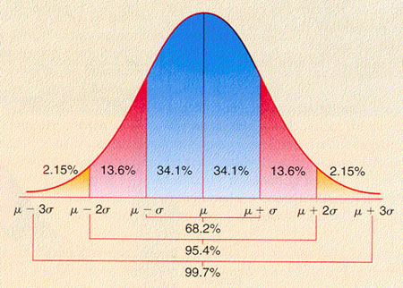
I reopen this threat because the new release of IPC-7352 changes the fabrication tolerances and the placement tolerances to 0.00. Due to this the negative values of the solder joints change to 0.00, as well. I can understand the reason to modify the fabrication tolerance value, it has a lot of sense. The pcb manufacturer applies a correction factor to the pcb due to the etching. Creating a footprint with a fabrication tolerance is to apply twice this tolerance. My question is related to the placement tolerance. Untill now this value was 0.025mm and I cannot understand the reason to modify it to 0.00. For example if a P&P machine has an accuracy of +/-50um (3 sigma), assuming that the component placement is a normal distribution  I think that it means that:
So the placement tolerance of +/- 0.025 mm is not a value far from the reality. Many thanks for help to all of you. Regards. David
|
|
 |
|
Tom H 
Admin Group 

Joined: 05 Jan 2012 Location: San Diego, CA Status: Offline Points: 6012 |
 Post Options Post Options
 Thanks(0) Thanks(0)
 Quote Quote  Reply Reply
 Posted: 10 Feb 2023 at 11:43am Posted: 10 Feb 2023 at 11:43am |
|
Today's pick & place machines have a tolerance of +/- 0.01 mm.
How old is the image that you posted? The V23 footprint expert allows the user to edit that assembly tolerance to match the age of the machines you use. However, the pad stack calculations are so subtle that the difference between 0.025 assembly tolerance and 0.00 is too small to be concerned. |
|
 |
|
Post Reply 
|
|
| Tweet |
| Forum Jump | Forum Permissions  You cannot post new topics in this forum You cannot reply to topics in this forum You cannot delete your posts in this forum You cannot edit your posts in this forum You cannot create polls in this forum You cannot vote in polls in this forum |