
 |

|
Axial Vertical Mount |
Post Reply 
|
| Author | |
mahmoodv99 
Advanced User 
Joined: 16 Jan 2016 Status: Offline Points: 93 |
 Post Options Post Options
 Thanks(0) Thanks(0)
 Quote Quote  Reply Reply
 Topic: Axial Vertical Mount Topic: Axial Vertical MountPosted: 31 May 2016 at 11:03pm |
|
How create Axial Component footprint with Vertical mount option ?
|
|
 |
|

|
|
 |
|
Tom H 
Admin Group 

Joined: 05 Jan 2012 Location: San Diego, CA Status: Offline Points: 5989 |
 Post Options Post Options
 Thanks(0) Thanks(0)
 Quote Quote  Reply Reply
 Posted: 01 Jun 2016 at 5:57am Posted: 01 Jun 2016 at 5:57am |
|
We use FP Designer to create both Vertical Mount Resistors and Lay Down Radial Lead capacitors.
|
|
 |
|
mahmoodv99 
Advanced User 
Joined: 16 Jan 2016 Status: Offline Points: 93 |
 Post Options Post Options
 Thanks(0) Thanks(0)
 Quote Quote  Reply Reply
 Posted: 01 Jun 2016 at 7:56pm Posted: 01 Jun 2016 at 7:56pm |
|
How Calculate pitch and height ?
No option in axial lead form calculator for vertical mount. It is available in LP calculator.. why not add in automatic library creation ?
|
|
 |
|
Tom H 
Admin Group 

Joined: 05 Jan 2012 Location: San Diego, CA Status: Offline Points: 5989 |
 Post Options Post Options
 Thanks(0) Thanks(0)
 Quote Quote  Reply Reply
 Posted: 02 Jun 2016 at 7:29am Posted: 02 Jun 2016 at 7:29am |
|
These are the top 10 Library Expert develop items right now · Preferences: o Added SMD Proportional Pad Stack mathematical model for land pattern calculation · FP Designer: o Added irregular pad shape o Added irregular package body shape · Calculator: o Axial Lead component family – added auto-calculation of lead pitch o Added lay down Radial Lead component families o Added Standup Axial Lead component families · 3D STEP: o Added lay down Radial Lead component families o Added Standup Axial Lead component families |
|
 |
|
mahmoodv99 
Advanced User 
Joined: 16 Jan 2016 Status: Offline Points: 93 |
 Post Options Post Options
 Thanks(0) Thanks(0)
 Quote Quote  Reply Reply
 Posted: 02 Jun 2016 at 8:43pm Posted: 02 Jun 2016 at 8:43pm |
|
Its OK, but where is the option to calculate axial vertical mount pitch and height ?

|
|
 |
|
Tom H 
Admin Group 

Joined: 05 Jan 2012 Location: San Diego, CA Status: Offline Points: 5989 |
 Post Options Post Options
 Thanks(0) Thanks(0)
 Quote Quote  Reply Reply
 Posted: 02 Jun 2016 at 8:58pm Posted: 02 Jun 2016 at 8:58pm |
|
The height is the axial lead body length plus the lead bend radius. That is suggesting that you're going to mount the body flush with the PCB surface. |
|
 |
|
mahmoodv99 
Advanced User 
Joined: 16 Jan 2016 Status: Offline Points: 93 |
 Post Options Post Options
 Thanks(0) Thanks(0)
 Quote Quote  Reply Reply
 Posted: 02 Jun 2016 at 9:09pm Posted: 02 Jun 2016 at 9:09pm |
|
How calculate bend radius and pitch ?
|
|
 |
|
Tom H 
Admin Group 

Joined: 05 Jan 2012 Location: San Diego, CA Status: Offline Points: 5989 |
 Post Options Post Options
 Thanks(0) Thanks(0)
 Quote Quote  Reply Reply
 Posted: 03 Jun 2016 at 1:41pm Posted: 03 Jun 2016 at 1:41pm |
|
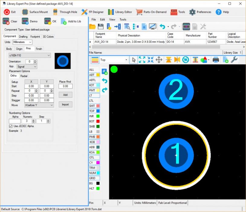
The pin pitch is 50% of the axial lead body round up to the nearest 1 mm or 0.1" grid (depending on if you design in millimeters or mil units. The total Height is the body plus the lead bend. Get a axial lead part and bend the lead how you want it and measure it. The Pin Pitch: Here is a screenshot from FP Designer and the grid display is 1 mm so the pin pitch = 3 mm  |
|
 |
|
Post Reply 
|
|
| Tweet |
| Forum Jump | Forum Permissions  You cannot post new topics in this forum You cannot reply to topics in this forum You cannot delete your posts in this forum You cannot edit your posts in this forum You cannot create polls in this forum You cannot vote in polls in this forum |