Axial Vertical Mount
Printed From: PCB Libraries Forum
Category: PCB Footprint Expert
Forum Name: Questions & Answers
Forum Description: issues and technical support
URL: https://www.PCBLibraries.com/forum/forum_posts.asp?TID=1899
Printed Date: 08 Jan 2026 at 4:16am
Topic: Axial Vertical Mount
Posted By: mahmoodv99
Subject: Axial Vertical Mount
Date Posted: 31 May 2016 at 11:03pm
|
How create Axial Component footprint with Vertical mount option ? |
Replies:
Posted By: Tom H
Date Posted: 01 Jun 2016 at 5:57am
|
We use FP Designer to create both Vertical Mount Resistors and Lay Down Radial Lead capacitors. ------------- Stay connected - follow us! https://twitter.com/PCBLibraries" rel="nofollow - X - http://www.linkedin.com/company/pcb-libraries-inc-/" rel="nofollow - LinkedIn |
Posted By: mahmoodv99
Date Posted: 01 Jun 2016 at 7:56pm
|
How Calculate pitch and height ? No option in axial lead form calculator for vertical mount. It is available in LP calculator.. why not add in automatic library creation ?
|
Posted By: Tom H
Date Posted: 02 Jun 2016 at 7:29am
|
These are the top 10 Library Expert develop items right now · Preferences: o Added SMD Proportional Pad Stack mathematical model for land pattern calculation · FP Designer: o Added irregular pad shape o Added irregular package body shape · Calculator: o Axial Lead component family – added auto-calculation of lead pitch o Added lay down Radial Lead component families o Added Standup Axial Lead component families · 3D STEP: o Added lay down Radial Lead component families o Added Standup Axial Lead component families ------------- Stay connected - follow us! https://twitter.com/PCBLibraries" rel="nofollow - X - http://www.linkedin.com/company/pcb-libraries-inc-/" rel="nofollow - LinkedIn |
Posted By: mahmoodv99
Date Posted: 02 Jun 2016 at 8:43pm
Its OK, but where is the option to calculate axial vertical mount pitch and height ?
|
Posted By: Tom H
Date Posted: 02 Jun 2016 at 8:58pm
|
The height is the axial lead body length plus the lead bend radius. That is suggesting that you're going to mount the body flush with the PCB surface. ------------- Stay connected - follow us! https://twitter.com/PCBLibraries" rel="nofollow - X - http://www.linkedin.com/company/pcb-libraries-inc-/" rel="nofollow - LinkedIn |
Posted By: mahmoodv99
Date Posted: 02 Jun 2016 at 9:09pm
| How calculate bend radius and pitch ? |
Posted By: Tom H
Date Posted: 03 Jun 2016 at 1:41pm
|
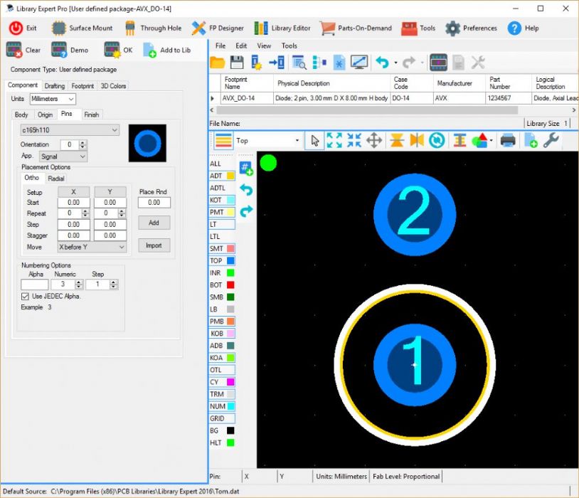
The pin pitch is 50% of the axial lead body round up to the nearest 1 mm or 0.1" grid (depending on if you design in millimeters or mil units. The total Height is the body plus the lead bend. Get a axial lead part and bend the lead how you want it and measure it. The Pin Pitch: Here is a screenshot from FP Designer and the grid display is 1 mm so the pin pitch = 3 mm  ------------- Stay connected - follow us! https://twitter.com/PCBLibraries" rel="nofollow - X - http://www.linkedin.com/company/pcb-libraries-inc-/" rel="nofollow - LinkedIn |