

|
|
Round vs Rectangular PTH Calculations |
Post Reply 
|
| Author | |
rickdehart 
Advanced User 

Joined: 18 Apr 2012 Location: Austin, TX Status: Offline Points: 184 |
 Post Options Post Options
") Thanks(0) Thanks(0)
 Quote Reply Quote Reply
 Topic: Round vs Rectangular PTH Calculations Topic: Round vs Rectangular PTH CalculationsPosted: 09 Nov 2012 at 12:14pm |
|
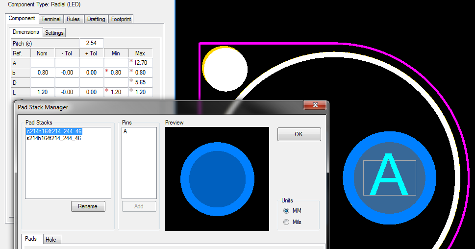
Can anyone tell me why there is a difference in the land size between a 1.44mm round and a 0.8x1.2mm rectanular pin? I am using the proportional enviorment. The Finished hole calculates out the same 1.64mm, but the land is 2.49mm for round and 2.14mm for rectanular. I put this on the LP Wizard Forum, but I see Footprint Expert is using the same calculations. |
|
 |
|

|
|
|
|
|
Jeff.M
Admin Group 

Joined: 16 May 2012 Location: San Diego Status: Offline Points: 499 |
Post Options
Thanks(0)
Quote Reply
Posted: 09 Nov 2012 at 1:35pm |
|
Since there is currently no component in FPX that allows both round and rectangular leads (just round and square) I checked this out using the Axial calculator for the round lead and a DIP for the rectangular lead with a proportional environment in both cases.
The results were as follows: 1.44mm round lead produces as 1.6mm hole and a 2.4mm pad; 0.8 X 1.2mm lead produces a 2.2mm hole (size based on the diagonal of the lead) and a 2.7mm pad. These results are pretty much as expected but not the results you report. Can you explain the method you used to arrive at the values you provided?
|
|
|
|
|
rickdehart
Advanced User
Joined: 18 Apr 2012 Location: Austin, TX Status: Offline Points: 184 |
Post Options
Thanks(0)
Quote Reply
Posted: 09 Nov 2012 at 1:47pm |
|
To keep things simple. I used the Radial (LED) and set b= 0.80, L=1.2 tolerance to +/-0, the round off to 0.01 and the placement to 0.01.
 |
|
|
|
|
Jeff.M
Admin Group
Joined: 16 May 2012 Location: San Diego Status: Offline Points: 499 |
Post Options
Thanks(0)
Quote Reply
Posted: 25 Feb 2013 at 9:35am |
|
It's because the elements that contribute to the Proportional calculation (Fabrication Allowance, Hole- over-Lead, etc.) are based solely on the lead 'b' dimension not the hole size. You'll notice that the Fabrication allowance for the two pads in your example are different. This is to prevent a slotted hole from having a disproportional fabrication allowance from an un-slotted hole with the same drill size.
|
|
|
|
|
Post Reply
|
|
| Tweet |
| Forum Jump | Forum Permissions You cannot post new topics in this forum You cannot reply to topics in this forum You cannot delete your posts in this forum You cannot edit your posts in this forum You cannot create polls in this forum You cannot vote in polls in this forum |


 Topic Options