|
|
Silk Legend For "Micro-miniature" Chip Components |
Post Reply 
|
| Author | |
mahmoodv99 
Advanced User 
Joined: 16 Jan 2016 Status: Offline Points: 93 |
 Post Options Post Options
") Thanks(1) Thanks(1)
 Quote Reply Quote Reply
 Topic: Silk Legend For "Micro-miniature" Chip Components Topic: Silk Legend For "Micro-miniature" Chip ComponentsPosted: 29 Feb 2016 at 8:49pm |
 |
|

|
|
|
|
|
Tom H
Admin Group 

Joined: 05 Jan 2012 Location: San Diego, CA Status: Offline Points: 6074 |
Post Options
Thanks(2)
Quote Reply
Posted: 29 Feb 2016 at 9:42pm |
|
IPC recommends that Legend outlines should not be placed under a component, especially a chip component.
Also, you can only do what you recommend on a 1206 or larger. You can't fit legend inside the pins of 0201 or 0402 or 0603. |
|
|
|
|
robmeyer
Advanced User
Joined: 04 Oct 2012 Status: Offline Points: 113 |
Post Options
Thanks(0)
Quote Reply
Posted: 13 Nov 2016 at 11:53pm |
|
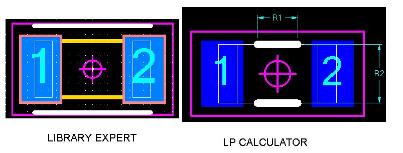
Hi, is there a way to get the "old" Library expert style for the Legend of chip components back? Now it is only possible to get this LP Calculator style like in the picture above.
Thanks Robert |
|
|
|
|
Tom H
Admin Group
Joined: 05 Jan 2012 Location: San Diego, CA Status: Offline Points: 6074 |
Post Options
Thanks(0)
Quote Reply
Posted: 14 Nov 2016 at 6:26am |
|
We have received a high volume of requests to remove Legend Markings for micro-miniature. You have 100% control of the Legend (Top & Bottom) and Assembly Drawing (Top & Bottom) in the "Drafting Symbols" tool bar menu. Watch this video for some tips - These are the marking shapes that are available for you to insert into the footprint. You select the Shape, Size, Line Width, Layer and Location. You can also fill or not fill closed polygons.  Here is an 0402 Chip Capacitor with Legend Lines that I quickly inserted a line shape, line length, line width, line location, rotation, layer that I wanted -  I could have selected a rectangle to completely encompass the entire part perimeter. But I choose lines that I could make any length I want. These lines are saved in the FPX file and you can edit them any time you want by simply selecting "Right Mouse Button > Shapes" and then double click on the Legend shape to modify it. We try to make Library Expert compatible for all users. |
|
|
|
|
Post Reply
|
|
| Tweet |
| Forum Jump | Forum Permissions You cannot post new topics in this forum You cannot reply to topics in this forum You cannot delete your posts in this forum You cannot edit your posts in this forum You cannot create polls in this forum You cannot vote in polls in this forum |


 Topic Options