OrCAD PCB - "Hidden & Deleted Pins" in TO DPAK
Printed From: PCB Libraries Forum
Category: PCB Footprint Expert
Forum Name: Questions & Answers
Forum Description: issues and technical support
URL: https://www.PCBLibraries.com/forum/forum_posts.asp?TID=845
Printed Date: 13 Jan 2026 at 9:29pm
Topic: OrCAD PCB - "Hidden & Deleted Pins" in TO DPAK
Posted By: dmonca
Subject: OrCAD PCB - "Hidden & Deleted Pins" in TO DPAK
Date Posted: 07 Feb 2013 at 12:42am
|
I am currently building our new footprint database for OrCAD PCB Editor and have some issues with the DPAK Footprint. 1. If I build the TO229P990X239-3_4 Footprint, which comes with the FPX library and has only pads 1, 3 and 4 visible, pin 2 also shows up in OrCAD PCB Editor. And even stranger, its orientation is horizontal.  2. If I create a new DPAK footprint, reorder the pin numbers, hide or remove pin number 4 (the pin in the middle) and save it to my own library, the pin shows up again when I reload the footprint.  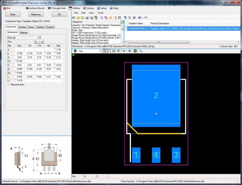 Not reordering the pin numbers does not change the described effect. The pin in the middle stil pops up again on reloading. Am I doing something wrong here? I downloaded the newest version (V2012-42) but there is no change in the described behaviour. Thanx for your help. Regards from Switzerland Daniel |
Replies:
Posted By: chrisa_pcb
Date Posted: 07 Feb 2013 at 12:21pm
| Fixed. It'll be in the next release. |
Posted By: dmonca
Date Posted: 08 Feb 2013 at 12:00am
Thank you very much  . I will try it, as soon as the next version is released . I will try it, as soon as the next version is released  |
Posted By: dmonca
Date Posted: 12 Feb 2013 at 12:02am
|
Sorry to bother you again. With the new Version (2012-43) the problem changed. The part from the fpx-library now builds correctly. However, the second problem that I described above is still present. The hidden pin still shows up on reloading the part. And if I build it, I get the hidden pin in the footprint |
Posted By: dmonca
Date Posted: 12 Feb 2013 at 12:05am
|
I forgot something: If I use the pin hiding feature for example on a soic footprint, it works correctly |
Posted By: Tom H
Date Posted: 19 Feb 2013 at 4:29pm
| Please download V44 and let us know if this was fixed. Thanks! |
Posted By: dmonca
Date Posted: 20 Feb 2013 at 5:48am
|
Hi Tom Nope. Still the same Problem with V44. And I now also get PAD-Designer error messages when building THT-Parts " PADSTACK ERRORS and WARNINGS: NCDRILL: Drill hole not defined. Required by BEGIN LAYER layer pads. NCDRILL: Drill hole not set. Required by internal layer pads. NCDRILL: Drill hole not defined. Required by END LAYER layer pads. " But I think this issue was addressed the post of "sgdavies" ( http://www.pcblibraries.com/forum/thru-hole-allegro-165_topic858.html" rel="nofollow - Thru_hole_Allegro_165 ) |
Posted By: rdl86626
Date Posted: 20 Feb 2013 at 9:19am
| I am going back to 43. I can not build QFP. It stalls |
Posted By: rdl86626
Date Posted: 20 Feb 2013 at 9:33am
|
I am going back to V43. I cannot build QFP. It stalls... |
Posted By: chrisa_pcb
Date Posted: 20 Feb 2013 at 10:06am
|
We had a problem in the packaging for V44 where the holes stopped coming through. That's the drill hole not defined issue. We'll have the fixed version out shortly.
As per your other issue, when I follow your instructions and bring the TO part into OrCAD PCB, the pins are showing up correctly. |
Posted By: Nick B
Date Posted: 20 Feb 2013 at 2:53pm
|
Please confirm this build of 2012.44 fixed this issue: http://www.pcblibraries.com/downloads/FPX%21Footprint_Expert_2012.asp" rel="nofollow - FPX Footprint Expert 2012.44
|
Posted By: dmonca
Date Posted: 21 Feb 2013 at 1:38am
|
Hi Nick The problem with the THT pads is gone with the latest build. Thanx! The middle pin still is reapearing. Here is what I do: - Create a new DPAK footprint as per TO252AA specifications - Mark the middle pin - Right-click and select "remove" - Import the Part in my library - Open another part from either my own or the fpx library (double-click on the name, so that it's footprint is visible) - Reload the part created before (also here: double-click for the footprint) -> Now the deleted pin in the middle is visible again I also found some new problem with renaming the Pins in the "Flange Mount (TO-220)" footprint. -> Mark a pin -> Rename it from "1" to "B", "2" to "C" and "3" to "E" via right-click and properties - Import the Part in my library - Open another part from either my own or the fpx library (double-click on the name, so that it's footprint is visible) - Reload the part created before (also here: double-click for the footprint) -> The renamed pins are showing "1", "2" and "3" again If I rename the pins on "Small Outlint Transistor (SOT23)" or "Small Outlint Transistor (SOT223)", everythingworks as expected and the pads keep their changed name. Regards Daniel |
Posted By: chrisa_pcb
Date Posted: 21 Feb 2013 at 11:55am
|
DPAK:
- Open another part from either my own or the fpx library (double-click on the name, so that it's footprint is visible)
- Reload the part created before (also here: double-click for the footprint) A new part gets created with a slightly different name when you successfully remove a pin. You may be opening your older part.
The only thing I can assume is that your old part that was created with the bug you haven't deleted and you're still trying to reopen it as if it were the new part. When you first generated the part, the pin was removed, was it not?
Seems like the same thing with the TO-220 tbh. If you import a part successfully, it can't change back unless you're looking at the old part.
|
Posted By: dmonca
Date Posted: 22 Feb 2013 at 12:51am
|
Hi Chris You were right with the DPAK. If I generate a new footprint from scratch it works fine. It did not do the trick on the TO220 though. Even after generating a new footprint and renaming the pins "BCE" they went back to "123". This does not happen on the new DPAK footprint btw. If I rename the pads they stay that way. And I also found another thing concerning the renumbering. After successfully generating the new DPAK footprint I wanted to renumber the pins. What then happend you can see on the following pictures: Original: 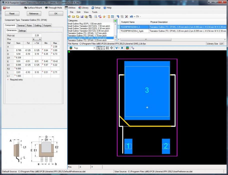 Renumbering: 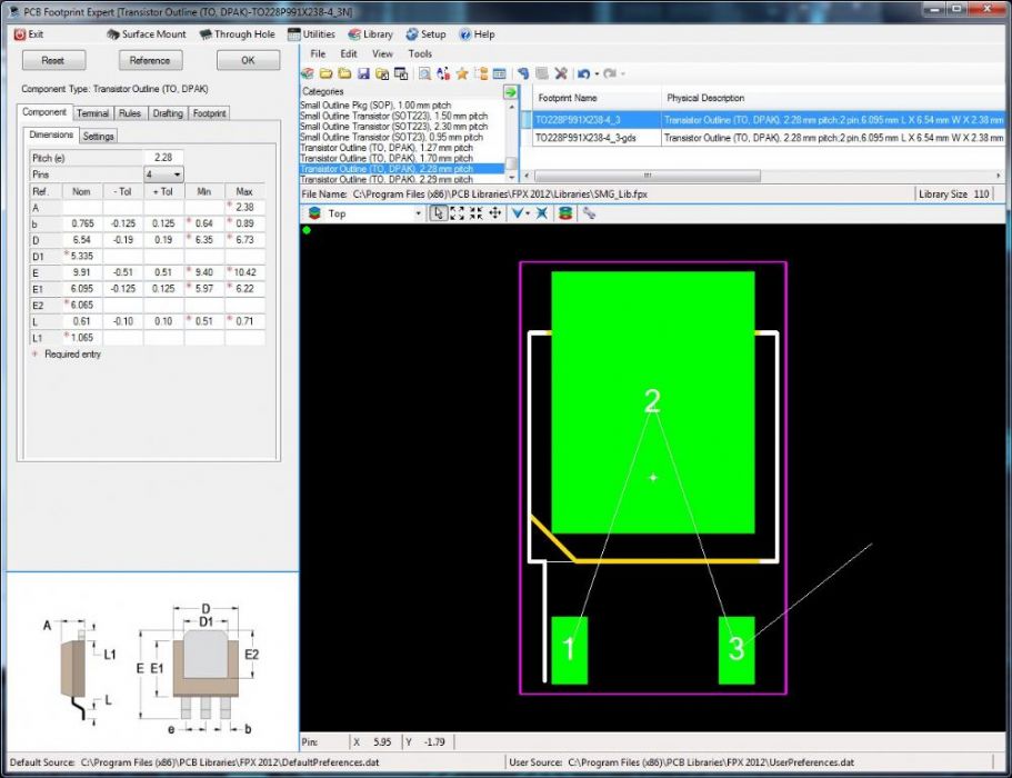 Result: 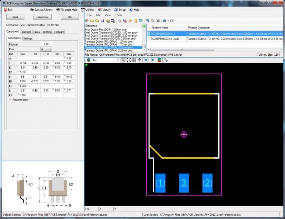 If I do the renumbering first and than remove the middle pad, then this pad showes up again on reloading the part. So we are back to the problem that I described at the beginning of this thread. Thanx for your help Regards Daniel |
Posted By: chrisa_pcb
Date Posted: 22 Feb 2013 at 1:29am
|
Ok.. this looks like a Jeff issue(he's calculator issues, i handle translations) and i'm going to pass it along and i'm sure he'll look at it in the morning. Pretty much everything with the graphics of the part, up to and including stuff not saving properly, is his area. The issue can be easily replicated by :
Step 1: I open say TO228P991X240-3_4 from the sm.fpx.
Step 2: I reorder the pins bottom left(1), Thermal Tab(2), Lower Right(3)
Step 3: I click Done Reordering.
Step 4: The Thermal Tab disappears, the bottom middle pin appears, and i have the same picture as the last image you posted, except pin 3 shows as pin 4.
I would think that no pins should disappear(along with one reappearing), and that it should reorder in the order specified.
The BCE thing I would imagine should happen post-reorder. The FPX, in its current form would need to first have the pins ordered and then named I would think. But Jeff can work that out.
|
Posted By: Jeff.M
Date Posted: 22 Feb 2013 at 3:16pm
|
This is inherent in the way reordering is done. This part already had a hidden pin (#2). When you reordered, whichever pin became pin 2 (was 4) disappeared. The way in which it will be 'fixed' is by un-hiding/removing pins prior to any reordering operation. Pins will then have to be hidden or removed again.
|
Posted By: dmonca
Date Posted: 25 Feb 2013 at 2:57am
|
Hi Jeff I just downloaded V45. Still no change in behaviour. As described at the end of my last post, if I restore the hidden pin first, do the renumbering, hide it again and save it to my library, this particular pin will reapear when I reload the part. So basically, once the pins are renumbered, somehow the "hidden/removed" attribute is ignored. Regards Daniel |
Posted By: Tom H
Date Posted: 25 Feb 2013 at 10:11am
|
Daniel, You must use the "Renumber Pin" feature before Hiding or Deleting pins. But, I see no reason to ever use Pin Renumber for DPAK's. Can you please attach a web-link to your DPAK datasheet so we can reproduce this issue and provide constructive feedback. You seem to be the only person with this issue so we need to reproduce what you're doing with "Step by Step" instructions that you provide. Thanks! |
Posted By: dmonca
Date Posted: 26 Feb 2013 at 2:03am
|
Hi Tom Well, the need for renumbering does not come from a specific part. It comes for the way how we designed parts in the library of OrCAD Capture (we do not use Capture CIS). Example: For the LM78xx voltage regulator we have one drawing in our Capture library. Where pin 1 is the input, pin 2 is ground and pin3 is the output. This numbering works for various cases (TO-220, TO3, ...) but not for DPAK and/or SOT223. So instead of creating another LM78xx for these footprints in Capture, we renumbered the pads of the footprint in PCB Editor. These renumbered footprints could then be used by other parts (LM79xx for example) as well. For the SOT223 case the renumbering in FootprintExpert worked, but not for the DPAK. I used the "renumber pin" feature on a new created part and before hiding pins. Here is what I do: - Create a new DPAK footprint as per TO252AA specifications (exact dimensions see attached pictures in previous posts) - Renumber the pins (left to right 1, 4, 3 for the small pads an 2 for the large pad) - Mark the middle pin (Nr.4), right-click and select "remove" - Import the Part in my library (the generated name is TO228P991X238-4_3) - Open another part from either my own or the fpe library (double-click on the name, so that it's footprint is visible) - Reload the part created before (also here: double-click for the footprint) -> Now the deleted pin in the middle is visible again Regards Daniel |
Posted By: Tom H
Date Posted: 26 Feb 2013 at 8:05am
|
Daniel, If you have a DPAK with pins 1, 2, 3 and you "Hide" pin 2 you will end up with pins 1, 3 There is no reason to renumber your pins if you know how to use the "Hide" and "Delete" features. I'm going to archive this entire thread today. |
Posted By: dmonca
Date Posted: 27 Feb 2013 at 6:03am
|
Hi Tom I guess we are not talking about the same thing right now. I guess you were looking at my last post with attached pictures, posted on 22 Feb 2013 at 8:51am. This "problem" indeed was my mistake since I was using "hide/remove" incorrectly. My main problem is shown at the end of the post that started this thread (see the following pictures). This is how the footprint looks before importing it to our library: 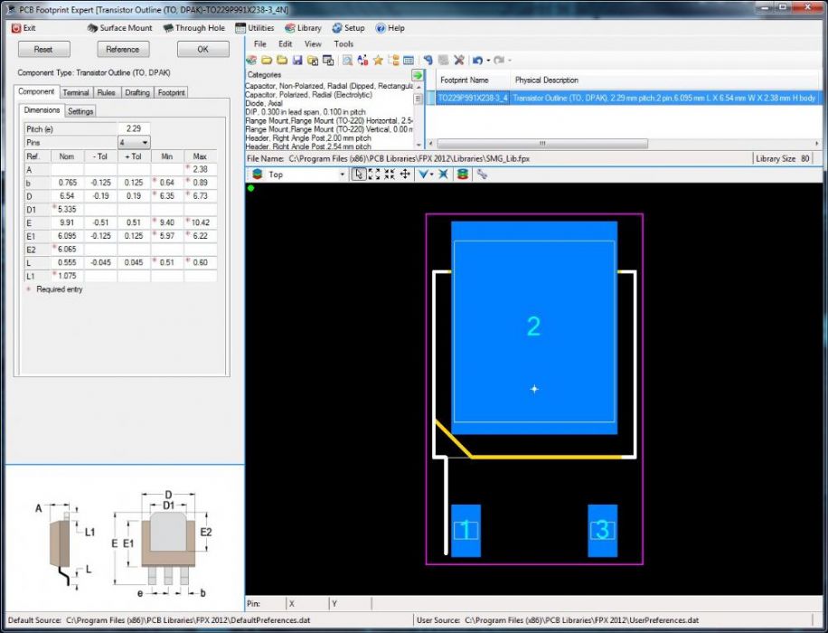 And this how it looks like when I reload it:  If I don't use the renumbering feature, then the middle pad stays removed. Today I tested it on a different Computer and got the same effect as described above. Regards Daniel |
Posted By: Tom H
Date Posted: 27 Feb 2013 at 7:09am
|
Daniel, Good catch! We'll fix this and send you a V46 Beta today for your approval. Thanks, Tom |
Posted By: Nick B
Date Posted: 27 Feb 2013 at 11:25pm
| please download and test 2012.46 beta http://www.pcblibraries.com/downloads/_FPX2012-46-altDL_7411988992001.zip" rel="nofollow - here and let us know if this was fixed. |
Posted By: dmonca
Date Posted: 28 Feb 2013 at 2:45am
|
Sorry, it did not work out. The pad is still showing up in the FPE Viewer after saving it to FPX. Daniel |
Posted By: Tom H
Date Posted: 28 Feb 2013 at 7:46am
|
Daniel, Are you saying that "Save to FPX" and retrieve from FPX is not working? Or building the DPAK in OrCAD PCB is not working? |
Posted By: dmonca
Date Posted: 01 Mar 2013 at 3:07am
|
Hi Tom, Yes, saving and retrieving from the fpx-library is the problem. Somehow FE seems to "forget", that a pin is removed when the numbering of the pins is not standard. As for the export to OrCAD: I built the part, with renumbering and removing the pad, and then let FE create the footprint (without saving it to any library first). The result is OK. Regards, Daniel |
Posted By: Tom H
Date Posted: 01 Mar 2013 at 7:47am
|
OK, we're categorizing this as user error in the tool. You're not supposed to renumber the pins the way you did 1, 4, 2 & 3 is the thermal pad and then delete Pin 4. You're supposed to take the normal part pins 1, 2, 3, 4 and "Remove" pin 2 and the final pin assignment will be 1, 2 & 3 is the thermal pad. |
Posted By: Jeff.M
Date Posted: 01 Mar 2013 at 8:30am
| Alternately, you can change the number of pins to 3 and double the pitch. |
Posted By: dmonca
Date Posted: 04 Mar 2013 at 6:32am
|
Hi Everybody In the final pin assignment, the thermal pad has be to pin 2. So using the standard footprint and then remove pin 2 does not help. What worked out, however, is setting the number of pins to 3 and doubling the pitch. Thanx for you help and your patience  Regards Daniel |