Calculator or Manufacturer's Suggested Footprint?
Printed From: PCB Libraries Forum
Category: PCB Footprint Expert
Forum Name: Questions & Answers
Forum Description: issues and technical support
URL: https://www.PCBLibraries.com/forum/forum_posts.asp?TID=1484
Printed Date: 31 Dec 2025 at 5:18pm
Topic: Calculator or Manufacturer's Suggested Footprint?
Posted By: gcary
Subject: Calculator or Manufacturer's Suggested Footprint?
Date Posted: 29 Nov 2014 at 7:15pm
|
When should I use the manufacturer's suggested footprint and when should I use the calculator? I just opened up the SM.fpx file and chose the SOD123 Case Code from Fairchild. That component is set to use the manufacturer's recommended dimensions. Are there any general guidelines one can follow to help decide whether to use calculator or manufacturer's suggested footprint? |
Replies:
Posted By: Tom H
Date Posted: 29 Nov 2014 at 10:40pm
|
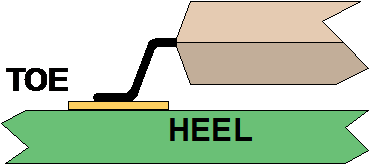
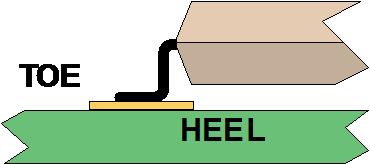
The rules for the Gull Wing Terminal Lead solder joint goal was created when the lead was long and it touched the PCB surface 0.5 - 0.1mm away from the package body and the "L" dimension had a robust tolerance. This is where the IPC-7351 footprint is best because the Heel is 70% of the solder joint strength.
Now the component manufacturers are bending the lead flat against the body of the component and the "L" dimension has a tight tolerance. Another name for this terminal is "Outward L". This is where the mfr. recommended footprint is best as most of the time there is no "Heel" so the mfr. will make the Side and Toe solder joint more robust.
Another example is 4-pin Corner Concave Oscillators. The component mfr.'s are pulling the lead inward and away from the body edge. The IPC-7351 calculates if the lead goes to the package edge (the lead terminals are recessed inward). So I always use the mfr. recommendation and they normally provide one.
Here is the Oscillator Mfr. picture. You can see that the Leads are "Pulled Back" from the edge.
------------- Stay connected - follow us! https://twitter.com/PCBLibraries" rel="nofollow - X - http://www.linkedin.com/company/pcb-libraries-inc-/" rel="nofollow - LinkedIn |


