|
|
Pin 1 Inside Courtyard? |
Post Reply 
|
| Author | |
AGONZ67 
Advanced User 

Joined: 30 Mar 2012 Status: Offline Points: 122 |
 Post Options Post Options
") Thanks(0) Thanks(0)
 Quote Reply Quote Reply
 Topic: Pin 1 Inside Courtyard? Topic: Pin 1 Inside Courtyard?Posted: 27 May 2014 at 4:36pm |
|
Is there a reason why these silkscreen dots are outside the courtyard? If they were moved just slightly to be near the long-side of the pin they could be inside the courtyard eliminating any chance of overlapping another part or feature. |
|
 |
|

|
|
|
|
|
Tom H
Admin Group 

Joined: 05 Jan 2012 Location: San Diego, CA Status: Offline Points: 6029 |
Post Options
Thanks(0)
Quote Reply
Posted: 27 May 2014 at 5:04pm |
|
For PADS Layout the Pin 1 Dots are Attributes and can be freely moved in the PCB layout. What CAD tool do you use? |
|
|
|
|
AGONZ67
Advanced User
Joined: 30 Mar 2012 Status: Offline Points: 122 |
Post Options
Thanks(0)
Quote Reply
Posted: 28 May 2014 at 8:44am |
|
Mainly PADS/Expedition. I was just thinking if it was already inside the courtyard, you would never have to touch it again.
|
|
|
|
|
Tom H
Admin Group
Joined: 05 Jan 2012 Location: San Diego, CA Status: Offline Points: 6029 |
Post Options
Thanks(0)
Quote Reply
Posted: 28 May 2014 at 10:15am |
|
But there is always a Silkscreen Line the full length of Pin 1 to denote Pin 1 location polarity. The dot was added because of high customer demand and it's in addition to the silkscreen line by Pin 1. Would you like a new feature that removes the line and replaces it with a Dot? Or do you want both the Pin 1 Dot and the Line? |
|
|
|
|
Matthew Lamkin
Advanced User
Joined: 02 Oct 2012 Status: Offline Points: 284 |
Post Options
Thanks(0)
Quote Reply
Posted: 03 Jun 2014 at 3:58am |
|
I'd like to remove the dot full stop
 If it is outside the courtyard it can cover the pads of another component, obviously this is unwanted. The component should be "as is" when placed, we should not have to move the pin 1 marker, so containing the marker within the courtyard outline is best. So a feature that removes the dot and leaves only the line would be preferred over one that removes the line and leaves a dot. |
|
|
|
|
Tom H
Admin Group
Joined: 05 Jan 2012 Location: San Diego, CA Status: Offline Points: 6029 |
Post Options
Thanks(1)
Quote Reply
Posted: 03 Jun 2014 at 6:34am |
|
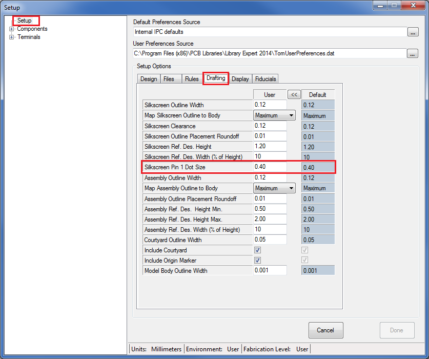
You can turn off any drafting item by changing the line width or size to 0 (zero) in User Preferences.
|
|
|
|
|
Tom H
Admin Group
Joined: 05 Jan 2012 Location: San Diego, CA Status: Offline Points: 6029 |
Post Options
Thanks(1)
Quote Reply
Posted: 03 Jun 2014 at 7:08am |
|
I forgot to ask about a possible new feature for Silkscreen Outlines.
Would you like the ability to have 3 different Silkscreen Outline options?
This question will be on our next Poll so we can see if there is a demand for this new feature. |
|
|
|
|
Matthew Lamkin
Advanced User
Joined: 02 Oct 2012 Status: Offline Points: 284 |
Post Options
Thanks(0)
Quote Reply
Posted: 03 Jun 2014 at 7:35am |
|
That would be good.
Ideally I'd prefer the silkscreen outline to be outside the pads and inside the placement outline. To do away with additional lines (like dots) and have a simple mitre on chips to denote pin 1. That keeps a simple continuous outline. So option 2 I think. Cheers Tom. |
|
|
|
|
Tom H
Admin Group
Joined: 05 Jan 2012 Location: San Diego, CA Status: Offline Points: 6029 |
Post Options
Thanks(0)
Quote Reply
Posted: 03 Jun 2014 at 7:43am |
|
If you choose to have the silkscreen Outside the pads and wrapped all the way around the part you could potentially remove the placement courtyard and use the silkscreen outline instead. But if you want both outlines, the courtyard will automatically adjust itself to be greater or equal to the silkscreen outline. The courtyard will never be "inside" the silkscreen outline. |
|
|
|
|
Matthew Lamkin
Advanced User
Joined: 02 Oct 2012 Status: Offline Points: 284 |
Post Options
Thanks(0)
Quote Reply
Posted: 03 Jun 2014 at 7:45am |
|
In CADSTAR the silkscreen outline is not shown in the external router so it needs the placement outline, if they are in the same place they cancel each other out when moving so its best slightly inside.
|
|
|
|
|
Post Reply
|
|
| Tweet |
| Forum Jump | Forum Permissions You cannot post new topics in this forum You cannot reply to topics in this forum You cannot delete your posts in this forum You cannot edit your posts in this forum You cannot create polls in this forum You cannot vote in polls in this forum |


 Topic Options