
 |

|
GPS-PA6B |
Post Reply 
|
| Author | |
hakaday 
Active User 
Joined: 06 Dec 2012 Status: Offline Points: 10 |
 Post Options Post Options
 Thanks(0) Thanks(0)
 Quote Quote  Reply Reply
 Topic: GPS-PA6B Topic: GPS-PA6BPosted: 08 Dec 2012 at 2:39am |
|
Hi all
I haven't done any PCB related work for about 10 years. I would like to layout a GPS board based on the PA6B GPS module from GTop and do it once with the correct footprints. How does one define a custom component or which footprint should one use to start a footprint for this device. I'm using the freeware version for the moment. The datasheet for the device is located here: http://www.gtop-tech.com/en/product/GPS_Modules_PA6B.html Thanks for your help. |
|
 |
|

|
|
 |
|
Tom H 
Admin Group 

Joined: 05 Jan 2012 Location: San Diego, CA Status: Offline Points: 5993 |
 Post Options Post Options
 Thanks(0) Thanks(0)
 Quote Quote  Reply Reply
 Posted: 08 Dec 2012 at 8:13am Posted: 08 Dec 2012 at 8:13am |
|
You need a little more information than the datasheet provides.
You need the physical component dimensions and/or the manufacturer recommended footprint dimensions. |
|
 |
|
hakaday 
Active User 
Joined: 06 Dec 2012 Status: Offline Points: 10 |
 Post Options Post Options
 Thanks(0) Thanks(0)
 Quote Quote  Reply Reply
 Posted: 08 Dec 2012 at 9:12am Posted: 08 Dec 2012 at 9:12am |
|
Thanks for the reply Tom.
The linked document is unfortunately all I have to work with. But I believe all the relevant data is in the datasheet. Steven |
|
 |
|
Tom H 
Admin Group 

Joined: 05 Jan 2012 Location: San Diego, CA Status: Offline Points: 5993 |
 Post Options Post Options
 Thanks(0) Thanks(0)
 Quote Quote  Reply Reply
 Posted: 08 Dec 2012 at 9:18am Posted: 08 Dec 2012 at 9:18am |
|
Not enough data to create the PCB library part.
|
|
 |
|
hakaday 
Active User 
Joined: 06 Dec 2012 Status: Offline Points: 10 |
 Post Options Post Options
 Thanks(1) Thanks(1)
 Quote Quote  Reply Reply
 Posted: 08 Dec 2012 at 9:49am Posted: 08 Dec 2012 at 9:49am |
|
|
|
 |
|
Tom H 
Admin Group 

Joined: 05 Jan 2012 Location: San Diego, CA Status: Offline Points: 5993 |
 Post Options Post Options
 Thanks(1) Thanks(1)
 Quote Quote  Reply Reply
 Posted: 08 Dec 2012 at 10:40am Posted: 08 Dec 2012 at 10:40am |
|
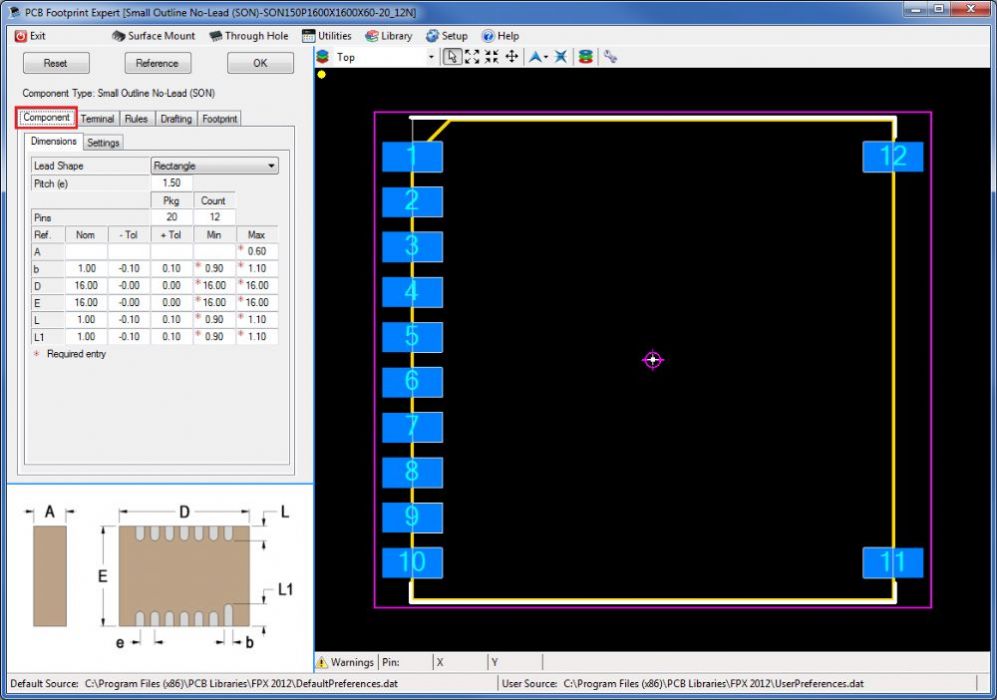
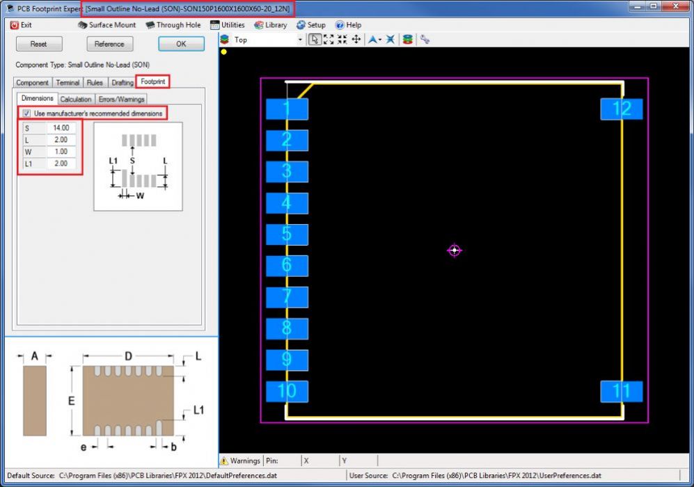
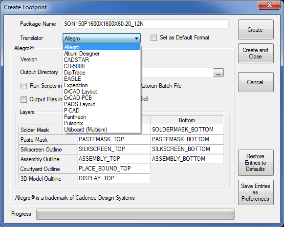
Using the current PCB Footprint Expert, I built this library part in less than 2 minutes using the component manufacturer's recommended solder pattern.
First I inserted the component dimensions and removed the deleted pins -  Then I selected the "Footprint" tab and inserted the component manufacturer's recommended solder pattern dimensions -  Then I selected the CAD tool of my choice and select the "Create" button - Bam!  |
|
 |
|
hakaday 
Active User 
Joined: 06 Dec 2012 Status: Offline Points: 10 |
 Post Options Post Options
 Thanks(0) Thanks(0)
 Quote Quote  Reply Reply
 Posted: 08 Dec 2012 at 11:05am Posted: 08 Dec 2012 at 11:05am |
|
Thanks Tom
Part of the problem was, I did not know which component to use the start the definition. The other problem that I had (have) is deletion of the pins. (I will follow the tutorial again.) I also tried to create the hole for the antenna which did not work to well. I will follow your example. Your help is much appreciated. |
|
 |
|
Tom H 
Admin Group 

Joined: 05 Jan 2012 Location: San Diego, CA Status: Offline Points: 5993 |
 Post Options Post Options
 Thanks(0) Thanks(0)
 Quote Quote  Reply Reply
 Posted: 08 Dec 2012 at 11:35am Posted: 08 Dec 2012 at 11:35am |
|
I used the SON (Small Outline No-lead) component family because it has the "Delete Pin" feature to remove the missing pins.
|
|
 |
|
Post Reply 
|
|
| Tweet |
| Forum Jump | Forum Permissions  You cannot post new topics in this forum You cannot reply to topics in this forum You cannot delete your posts in this forum You cannot edit your posts in this forum You cannot create polls in this forum You cannot vote in polls in this forum |