|
|
PCB Pad & Footprint Orientation |
Post Reply 
|
| Author | ||||||||||||||||||||||||||||||||||||||||||||||||||||||||||||||||||||||||||||||||||||||||||||||||||||||||||||||||||||||||||||||||||||||||||||||||||||||||||||||||||||||||||||||||||||||||||||||||||||||||||||||||||
Nick B 
Admin Group 
Joined: 02 Jan 2012 Status: Offline Points: 1966 |
 Post Options Post Options
") Thanks(0) Thanks(0)
 Quote Reply Quote Reply
 Topic: PCB Pad & Footprint Orientation Topic: PCB Pad & Footprint OrientationPosted: 16 Jan 2025 at 10:04pm |
|||||||||||||||||||||||||||||||||||||||||||||||||||||||||||||||||||||||||||||||||||||||||||||||||||||||||||||||||||||||||||||||||||||||||||||||||||||||||||||||||||||||||||||||||||||||||||||||||||||||||||||||||
|
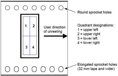
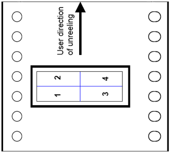
Printed circuit board technology uses geometry to define the rotational angle of every object in the PCB design. Objects use geometry to define the orientation starting at 0,0 which is located on the right center. Cartesian coordinates are also defined per the PCB or Footprint origin. Popular Pad and Footprint rotations are 0, 90, 180 and 270 degrees, but can be placed at any angle. Pad and Footprint orientations start at 0,0 and rotate counterclockwise. 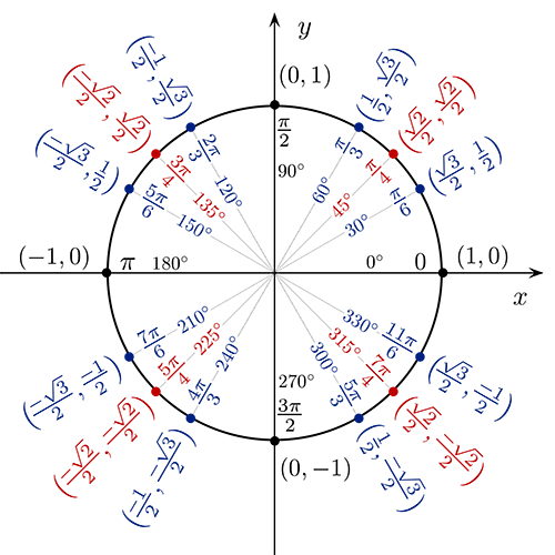 1. Pad Rotations Start at 0,0 in the Positive X Location Pad rotation follows geometry standards. 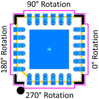 Footprint rotations are in 90° increments starting with the zero-component orientation per the IEC 61188-7 Rotation B released in 2007 with pin 1 in the Lower Left corner. IEC 61188-7 reflects the same zero component orientation documented in the IPC-SM-782 standard that was released in March 1987. The main reason to establish and follow a zero-component orientation is to help automate the assembly process. A known zero-component orientation will eliminate hours of research in PCB assembly trying to figure out the footprint rotations in the CAD library. IPC-7351 released in 2005 made a huge mistake by redefining pin 1 orientation to the Upper Left and broke an 18 standard where from 1987 – 2005 IPC defined the pin 1 orientation in the lower left. Also, the zero-component orientation should follow the Tape and Reel, Tube and Tray orientations defined by EIA. However, component manufacturer rotations vary from one mfr. to another for the same package type. A standard must be adhered to by component manufacturers. Here are the zero component orientations from IPC-7351, IEC 61188-7 and EIA-481-D.
Per all the JEDEC standard package definitions, quadrant 1 is where pin 1 should be located. IPC and IEC use consistent rotations throughout their standard where EIA uses multiple rotation variations.
This study concludes that the Zero Component output Orientation in the IPC Calculator should be 100% definable to allow the user to output any of the three industry standard rotations for CAD library construction. The only alternative is for the three standards organizations to collaborate on a single standard for the future. The IPC Calculator is being used all over the world. In the USA, military contractors, including General Dynamics in Canada, are asking for the IPC Calculator to output CAD library parts in the EIA-481-D rotation. In Japan, Germany, Australia and South Korea, IPC Calculator users are asking to output CAD library parts in the IEC 61188-7 rotation. The proposed IPC-7351C included Level A (current IPC standard) and Level B (IEC standard) component rotations. The main scope of zero-component orientations was to establish a consistent technique for the description of electronic component orientation, and their land pattern geometries, that facilitates and encourages a common data capture and transfer methodology amongst and between global trading partners. IPC, in conjunction with the International Electrotechnical Commission (IEC), have established several standards that are in the process of being coordinated. One of the standards is on the design of land patterns geometries (IPC-7351/IPC-7352/IEC 61188-5-1); the other set is on electronic description for data transfer between design and manufacturing (IPC-2581/IEC 61182-2). To maintain a consistent method where these two important standards describe the component mechanical outlines, and their respective mounting platforms, a single concept must be developed that takes into account various factors within the global community. Many large firms have spent millions of dollars creating and implementing their own unique standards for their own “Electronic Product Development Automation”. These standards are proprietary to each firm and are not openly shared with the rest of the industry. This has resulted in massive duplication of effort costing the industry millions of man hours in waste and creating industry chaos and global non-standardization. The industry associations responsible for component descriptions and tape and reel orientation have tried valiantly to influence the industry by making good standards that describe the component outlines and how they should be positioned in the delivery system to the equipment on the manufacturing floor. Suppliers of parts have either not adhered to the recommendations or have misunderstood the intent and provided their products in different orientations. The Land pattern standards put an end to the “Proprietary Intellectual Property” and introduce a world standard so every electronics firm can benefit from Electronic Product Development Automation. The data format standards (IPC-2581 and IEC 61182-2) are an open database XML software code that is neutral to all the various CAD ASCII formats. For true machine automation to exist, the world desperately needs a neutral CAD database format that all PCB manufacturing machines can read. The main purpose of creating the land pattern standards is to achieve reliable solder joint formation platforms; the reason for developing the data transfer structure is to improve the efficiency with which engineering intelligence is converted to manufacturing reality. Even if the neutral CAD format can drive all the manufacturing machines, it would be meaningless unless the component description standard for CAD land patterns was implemented with some consistency. Zero Component Orientation has a key role in machine automation. The obvious choice for global standardization for EE hardware engineering, PCB design layout, manufacturing, assembly and testing processes is to incorporate the standard land pattern conventions. Any other option continues the confusion and additional manual hours of intervention in order to achieve the goals of automation. In addition, the ease of having one system export a file so that another system can accomplish the work may require unnecessary manipulation of the neutral format in order to meet the object of clear, unambiguous software code. The design of any assembly will continue to permit arrangement and orientation of components at any orientation consistent with design standards. Starting from a commonly understood data capture concept will benefit the entire supply chain. Here is the flow for zero-component orientation and the counterclockwise rotation of a standard 8-pin SOIC. 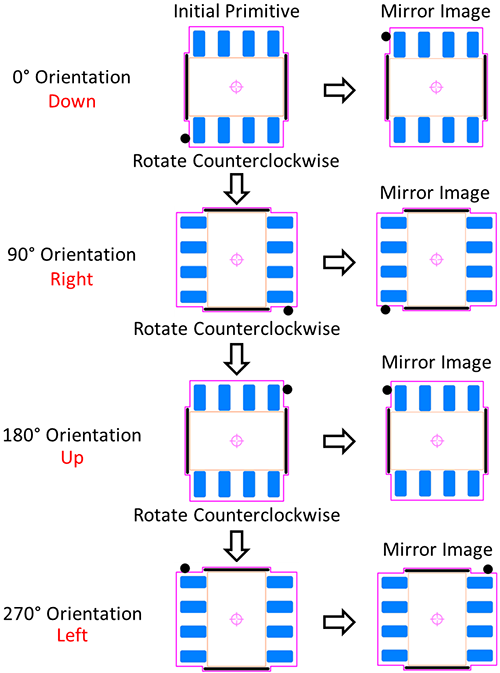  PCB Footprint Expert The Footprint Expert reliably creates footprints and 3D STEP models with your preferred rotation. Modify any setting, then batch-rebuild your entire library! The Footprint Expert helps you create flawless PCB designs much more efficiently! Get your FREE Footprint Calculator or Footprint Expert Evaluation License: Call: 847-557-2300 |
||||||||||||||||||||||||||||||||||||||||||||||||||||||||||||||||||||||||||||||||||||||||||||||||||||||||||||||||||||||||||||||||||||||||||||||||||||||||||||||||||||||||||||||||||||||||||||||||||||||||||||||||||
 |
||||||||||||||||||||||||||||||||||||||||||||||||||||||||||||||||||||||||||||||||||||||||||||||||||||||||||||||||||||||||||||||||||||||||||||||||||||||||||||||||||||||||||||||||||||||||||||||||||||||||||||||||||

|
||||||||||||||||||||||||||||||||||||||||||||||||||||||||||||||||||||||||||||||||||||||||||||||||||||||||||||||||||||||||||||||||||||||||||||||||||||||||||||||||||||||||||||||||||||||||||||||||||||||||||||||||||
|
||||||||||||||||||||||||||||||||||||||||||||||||||||||||||||||||||||||||||||||||||||||||||||||||||||||||||||||||||||||||||||||||||||||||||||||||||||||||||||||||||||||||||||||||||||||||||||||||||||||||||||||||||
|
SDTKO
Active User 
Joined: 11 Dec 2019 Status: Offline Points: 31 |
Post Options
Thanks(0)
Quote Reply
Posted: 17 Jan 2025 at 1:12am |
|||||||||||||||||||||||||||||||||||||||||||||||||||||||||||||||||||||||||||||||||||||||||||||||||||||||||||||||||||||||||||||||||||||||||||||||||||||||||||||||||||||||||||||||||||||||||||||||||||||||||||||||||
|
Is there an actual standard for bottom side zero component location and rotation direction? I feel like this just depends on how the CAD tool happens to implement it. There are tools that do it like this for example: 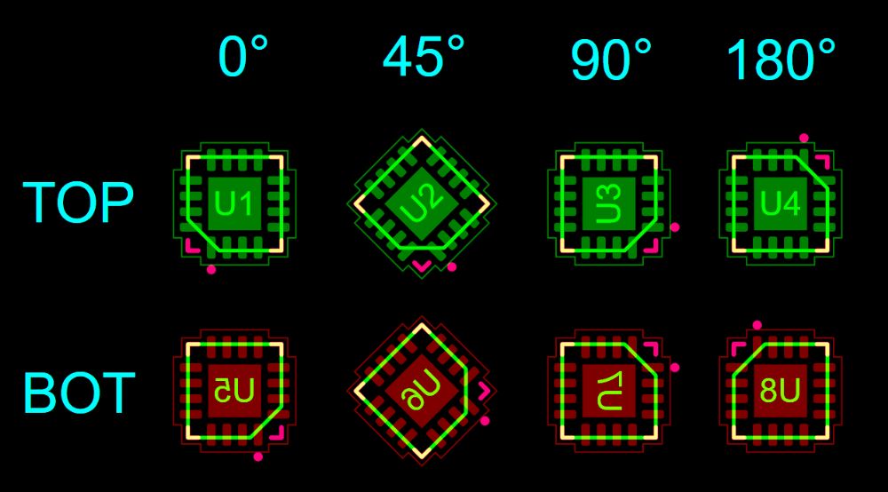 |
||||||||||||||||||||||||||||||||||||||||||||||||||||||||||||||||||||||||||||||||||||||||||||||||||||||||||||||||||||||||||||||||||||||||||||||||||||||||||||||||||||||||||||||||||||||||||||||||||||||||||||||||||
|
||||||||||||||||||||||||||||||||||||||||||||||||||||||||||||||||||||||||||||||||||||||||||||||||||||||||||||||||||||||||||||||||||||||||||||||||||||||||||||||||||||||||||||||||||||||||||||||||||||||||||||||||||
|
Tom H
Admin Group

Joined: 05 Jan 2012 Location: San Diego, CA Status: Offline Points: 5853 |
Post Options
Thanks(0)
Quote Reply
Posted: 17 Feb 2025 at 4:50pm |
|||||||||||||||||||||||||||||||||||||||||||||||||||||||||||||||||||||||||||||||||||||||||||||||||||||||||||||||||||||||||||||||||||||||||||||||||||||||||||||||||||||||||||||||||||||||||||||||||||||||||||||||||
|
In PADS Layout, the Bottom (Opposite) Side footprint rotation is clockwise.
The Top Side footprints rotate counterclockwise. It could be different for each CAD tool. |
||||||||||||||||||||||||||||||||||||||||||||||||||||||||||||||||||||||||||||||||||||||||||||||||||||||||||||||||||||||||||||||||||||||||||||||||||||||||||||||||||||||||||||||||||||||||||||||||||||||||||||||||||
|
||||||||||||||||||||||||||||||||||||||||||||||||||||||||||||||||||||||||||||||||||||||||||||||||||||||||||||||||||||||||||||||||||||||||||||||||||||||||||||||||||||||||||||||||||||||||||||||||||||||||||||||||||
|
dramos
Advanced User 
Joined: 18 Feb 2021 Status: Offline Points: 71 |
Post Options
Thanks(0)
Quote Reply
Posted: 22 hours 34 minutes ago at 7:04am |
|||||||||||||||||||||||||||||||||||||||||||||||||||||||||||||||||||||||||||||||||||||||||||||||||||||||||||||||||||||||||||||||||||||||||||||||||||||||||||||||||||||||||||||||||||||||||||||||||||||||||||||||||
|
Dear Nick and Team, In our company, there is a great discussion about the pin1 orientation. To use IPC-7351 or to use IEC-61188-7. I've read the article of the Top, and at the end my conclusions are: - IEC-61188-7, is and standard very extended in Europe and some countries in ASIA that over the years has been consistent, has not changed. In other hand IPC-7351 modified the criteria from IPC-SM-781. In the article is mentioned that it was an error, could you tell me an example? I have not the experience of PCBFE. - IEC-61188-7, is more close to the IEC-481 from the point of view of the pin1 on reel. - JEDEC has pin1 in cuadrant 1. Is there anything else that I missed that I could argue to convince to my colleagues to use IEC-61188-7? That's true that PCBFE gives us the possibility to configure it, but we would like to use the same .opt file on each site of the company. Thanks for your comments. david |
||||||||||||||||||||||||||||||||||||||||||||||||||||||||||||||||||||||||||||||||||||||||||||||||||||||||||||||||||||||||||||||||||||||||||||||||||||||||||||||||||||||||||||||||||||||||||||||||||||||||||||||||||
|
||||||||||||||||||||||||||||||||||||||||||||||||||||||||||||||||||||||||||||||||||||||||||||||||||||||||||||||||||||||||||||||||||||||||||||||||||||||||||||||||||||||||||||||||||||||||||||||||||||||||||||||||||
|
Tom H
Admin Group
Joined: 05 Jan 2012 Location: San Diego, CA Status: Offline Points: 5853 |
Post Options
Thanks(0)
Quote Reply
Posted: 20 hours 18 minutes ago at 9:20am |
|||||||||||||||||||||||||||||||||||||||||||||||||||||||||||||||||||||||||||||||||||||||||||||||||||||||||||||||||||||||||||||||||||||||||||||||||||||||||||||||||||||||||||||||||||||||||||||||||||||||||||||||||
|
You need to know why IPC-7351 zero component orientation came into existence.
I joined the 1-13 IPC Land Pattern Committee in 1999 to help Dieter Bergman with a IPC-SM-782 software calculator to replace the IPC on-line land pattern calculator that was very expensive for IPC to maintain. My first goal was in 2000 to transition from using imperial units to designing PCB library parts and PCB layout using the metric measurement system. The first calculator Jeff and I created was an Excel spreadsheet with called LandCalc. It was primarily SMD and only supported metric units. This was to run all tests to ensure the IPC mathematical model for min/max calculations was perfect. The first calculators only had one rotation 'Pin 1 Lower Left' which was what the IPC-SM-782 supported since March 1987. After all, it was just an Excel spreadsheet and we didn't have the luxury of multiple rotations. It took 2 years to add all the component families and finalize the min/max mathematical model. Then thanks to Philip Restall in the UK, we added a CAD tool translator for Mentor Graphics PADS. PADS was ASCII format so it was easy to figure out and we renamed the Excel spreadsheet to LandWiz. We freely distributed LandWiz on a website www.pcbstandards.com and had lots of downloads. Then in 2003 we started writing code for the first software program which was Land Pattern Wizard. We shortened the name to LP Wizard. It was unique because there was only one footprint rotation 'Pin 1 Lower Left' because user feedback wanted us to fully dimension the resulting footprint to make it easy to QC. Then IEC introduced the 3-Teir PCB library solution and we had to change everything to add the Least, Nominal and Most solder joint goals. This took another year to implement into the software tool. We completed LP Wizard in 2004 with 3-Teirs, lower left was the zero component orientation and metric units only. We delivered it to IPC to test and replace their on-line calculator. IPC was interested in getting volunteers involved in the approval process and were signing up volunteers quickly. We invited industry experts in join the IPC committee. Unfortunately, many of the volunteers turned out to be takers rather than givers. They attended meetings get information rather than provide information. IPC had the final 1-13 Land Pattern Committee meeting at the 2004 IPC APEX conference in Anaheim, CA. We invited everyone in the local area to attend, especially members of local IPC Designer Council members. I spoke at the local San Diego chapter meetings regarding this new technology and try to convince everyone to transition to the metric measurement system. One attendee at the meeting was Jami Smith. He liked to attend IPC Designer Council meetings to learn more about standards in the electronics industry. Jami said he was interested in helping with the new land pattern committee, but the committee had already completed their goal of upgrading IPC-SM-782 to IPC-7351. But there was one more meeting at IPC APEX in Anaheim, CA and Jami Smith attended the meeting. He was about 30 minutes late getting to the meeting and when he entered, he recognized me and sat next to me. I was running the projector through my lap top showing the committee the new LP Wizard software program and the IPC-7351 draft. 80% of the attendees at his final meeting were newbies who never attended a single Land Pattern meeting. They were just people who wanted to learn more about the new standard. Also, this was the first and last IPC Land Pattern Committee meeting that Jami Smith attended. We were all set to finalize the standard when Jami stood up to address the attendees. He claimed to have knowledge of EIA-481 and insisted that the EIA zero component orientation for pick and place machines was Pin 1 'Upper Left'. No one at the APEX meeting knew anything about EIA-481 so they took Jami's word that he was trying to contribute information that we were unaware of. Vern Solberg was one of the committee leaders and he suggested a committee vote from everyone in the room. Don't forget that 80% of the attendees had never attended a standards meeting before and they were asked to vote on an important subject. Karen McConnell the committee chairman was there and she agreed with Jami Smith. Then when everyone voted, they sided with Karen and Jami and that was the turning point for the IPC-7351 Zero Component Orientation. Jami Smith left the meeting and no one ever saw him again. But the damage was done. It took us 3 - 4 months to change all the footprint rotations in LP Wizard. IPC-7351 was released in 2005. IEC got involved and chastised IPC for changing the footprint rotation based on faulty information and a rash decision at a meeting that no one had the knowledge of what impact they had on the entire electronics industry. So IEC released the IEC 61188-7 which reverted back to IPC-SM-782 zero component orientation. Dieter Bergman and I had a conversation in 2008 about changing the zero component orientation for IPC-7351B, but Dieter said that once a standard is released it's very difficult to say you were wrong and here's the correction. Dieter shrugged his shoulders and said "Let the best standard win". However, in 2014 the IEC standard was winning and Dieter agreed to change the zero component orientation in the new IPC-7351C. We had the kick-off meeting at IPC headquarters the week of July 15 - 19. We created the entire framework for the new totally upgraded IPC-7351 standard. I left the meeting and flew back to San Diego, CA and immediately started working that weekend on Chapters 5 for surface mount and 6 for through-hole. The following week on July 23, Dieter Bergman passed away. This was a devasting loss to the electronics industry but I was inspired to carry the torch and spent the next year writing the IPC-7351C with Rainer Taube in Germany. We introduced IPC-7351C to the Land Pattern Committee in 2016 and we worked on refining it for 6 years. Then we found out that Dieter never had the approval by the IPC executive committee for IPC-7351C and they shelved it, never to be released. Bottom line is that the Pin 1 in the upper left for xero component orientation should have never been released and Jami Smith will go down in history for changing a standard that he had no business being involved in. Jami disappeared never to be heard from or seen again. And now you know - the rest of the story... |
||||||||||||||||||||||||||||||||||||||||||||||||||||||||||||||||||||||||||||||||||||||||||||||||||||||||||||||||||||||||||||||||||||||||||||||||||||||||||||||||||||||||||||||||||||||||||||||||||||||||||||||||||
|
||||||||||||||||||||||||||||||||||||||||||||||||||||||||||||||||||||||||||||||||||||||||||||||||||||||||||||||||||||||||||||||||||||||||||||||||||||||||||||||||||||||||||||||||||||||||||||||||||||||||||||||||||
|
Post Reply
|
|
| Tweet |
| Forum Jump | Forum Permissions You cannot post new topics in this forum You cannot reply to topics in this forum You cannot delete your posts in this forum You cannot edit your posts in this forum You cannot create polls in this forum You cannot vote in polls in this forum |


 Topic Options