PCB Libraries Forum Homepage
Forum Home Forum Home > PCB Footprint Expert > Features & Training > Options
  New Posts New Posts RSS Feed - Local & Global Calculator Options
  FAQ FAQ  Forum Search   Events   Register Register  Login Login

Local & Global Calculator Options

 Post Reply Post Reply
Author
Message
Nick B View Drop Down
Admin Group
Admin Group


Joined: 02 Jan 2012
Status: Offline
Points: 1941
Post Options Post Options   Thanks (0) Thanks(0)   Quote Nick B Quote  Post ReplyReply Direct Link To This Post Topic: Local & Global Calculator Options
    Posted: 12 hours 41 minutes ago at 1:19am
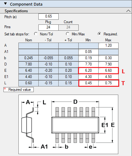
The Local Options are in the Footprint Expert standard component package calculators. These Options are used to test option features to experience the settings in real time. The user makes notes of the features they want to use in Global Options. Once all the Global Options are defined, the Local Options are only used for one of a kind footprint.

One of the most popular FAQs regarding using Local Options is "I set the Local Options to create a custom footprint and save the data to a FPX file library and when I reopen the footprint from the FPX library into the Viewer, all the Local Option Settings that were selected are reset to default Options".

The Local Option Settings are not saved to the FPX file library, except 3D STEP Colors, Footprint Rotation and Mfr. Recommended Footprint as noted by Bold Italic Characters.

Here are the Local Options in every standard package Calculator:
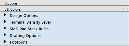

Options
 
  • Set the Pin 1 Orientation. Changes to this setting are saved to the FPX file library.
    • Lower Left - default setting
    • Lower Right
    • Upper Right
    • Upper Left
  • Origin - This is set locally and not saved to the FPX file library.
    • Center Of Extents - default setting
    • Pin 1
  • Pads On Assembly - This is set locally and not saved to the FPX file library.
    • None - default setting
    • Outline
    • Filled
  • Tabs On Assembly - This is set locally and not saved to the FPX file library.
    • None - default setting
    • Outline
    • Filled
  • Default Pad Shape - This is set locally and not saved to the FPX file library.
    • D-Shape
    • Oblong
    • Rectangle
    • Rounded Rectangle - default setting
  • Pin 1 Pad Shape - This is set locally and not saved to the FPX file library.
    • D-Shape
    • Oblong
    • Rectangle
    • Rounded Rectangle - default setting
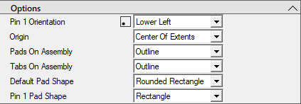
3D Colors - Any changes are saved to the FPX file library.
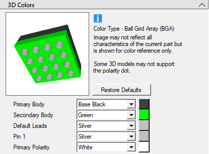
  • Set the Primary Body
  • Secondary Body
  • Default Leads
  • Pin 1
  • Primary Polarity
Design Options


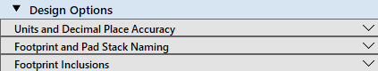
Units and Decimal Place Accuracy - These settings are not saved to FPX file library

  • Units - units are not saved to the FPX library
    • Millimeters - default setting
    • Micrometers
    • Mils
    • Inches
  • Specifications and Calculations
    • Minimum settings appear in the Calculators
      • 1 = 0.1
      • 2 = 0.01- default setting
      • 3 = 0.001
      • 4 = 0.0001
      • 5 = 0.00001
      • 6 = 0.000001
    • Maximum setting is the character limit in the Calculators
      • A setting of 3 will limit the calculator input values to 3 places to the right of the decimal point
  • Calculated Footprint
    • Pad Size roundoff
      • 1 = 0.1
      • 2 = 0.01- default setting
      • 3 = 0.001
      • 4 = 0.0001
      • 5 = 0.00001
      • 6 = 0.000001
    • Pad Place roundoff
      • 1 = 0.1
      • 2 = 0.01- default setting
      • 3 = 0.001
      • 4 = 0.0001
      • 5 = 0.00001
      • 6 = 0.000001
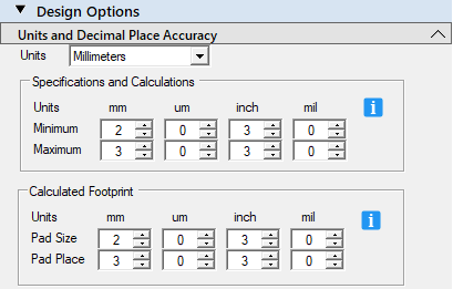
Footprint and Pad Stack Naming - These settings are not saved to FPX file library

  • Footprint Naming Convention
    • PCB Libraries (formally IPC-7351C and approved by the IPC Land Pattern Committee)
    • IPC-7351B
    • IPC-7352
  • Create Footprint Name Using (Units)
    • Millimeters - default setting
    • Micrometers
    • Mils
    • Inches
  • Replace Density Level Suffix With… - users can create their own Density Level
  • Pad Stack Naming Convention
    • IPC-7352 - default setting
    • IPC-7351B
  • Create Pad Stack Name Using (Units)
    • Millimeters - default setting
    • Micrometers
    • Mils
    • Inches
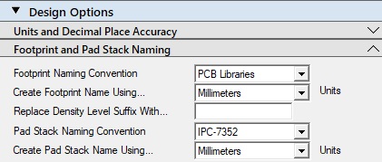
Footprint Inclusions

  • Ignore Manufacturer's Footprint Dimensions (for Batch Builds) - Default Off
  • Include Suffix in Footprint Name - Default On
  • Generate Solder Mask - Default On
  • Generate Surface Mount Paste Mask - Default On
  • Generate Through-hole Paste Mask - Default Off (Pin-in-Paste Technology 
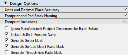
Terminal Density Level - These settings are not saved to FPX file library


  • Density Level (Suffix)
    • Least (L)
    • Nominal (N) - Default Setting
    • Most (M)
  • Courtyard to Body Excess
    • 0.20 - Default Setting
  • Courtyard to Pad Excess
    • 0.20 - Default Setting
  • Toe
  • Heel
  • Side
Terminal Lead image pop-out


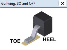
SMD Pad Stack Rules - These settings are not saved to FPX file library


  • Solder and Paste Masks - None of these settings are saved to FPX file library
    • Minimum Allowable Solder mask Web - 0.075 (default)
    • Solder Mask Annular Expansion (+/-) - 0.00 (default)
    • Paste Mask Annular Expansion (+/-) - unchecked default setting
    • Paste Mask (% of Pad Size) - 100% (default)
    • Set SM Grid Array Options in Terminal Density Settings
  • Corner Rounding
    • Corner Radius Size (% of Pad Width) - 25% (default)
    • Corner Radius Size Limit - 0.10 (default)
  • Manufacturing Tolerances
    • Fabrication Tol. (+/-) - 0.00 (default setting per IPC-7352)
    • Placement Tol. (+/-) - 0.00 (default setting per IPC-7352)
  • Minimum Trim and Spacing
    • Minimum Pad to Pad - 0.15 (default)
    • Minimum Pad to Thermal - 0.20 (default)
    • Minimum Trim Standoff Height - 0.03 (default)
      • This is used on Gullwing Terminal Leads to trim pads under packages with the PCB standoff of less than 0.03
  • Thermal Tabs
    • Thermal Tab Solder Mask Expansion (+/-) - 0.00 (default)
    • Thermal Tab Pattern Defined Solder Mask - Off (default)
    • Thermal Tab Paste Mask (%) - 60% (default)
    • Thermal Tab Minimum Pattern Space - 0.20 (default)
  • SMD and TH Miscellaneous
    • Cathode/Anode Pin Names 
      • Alphanumeric (default)
      • Numeric
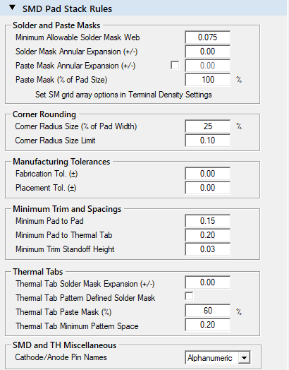
Drafting Options > Silkscreen - These settings are not saved to FPX file library

  • Outline Width 0.15 (default)
  • Clearance to Pads - 0.15 (default)
  • Map Outline to Body 
    • None
    • Minimum
    • Nominal 
    • Maximum (default)
    • Margin
  • Outline to Body Margin - 0.15 (default)
    • This is used when Map Outline to Body Margin is selected
  • Offset Outline Away From SM Body - On (default)
    • This converts the line origin from the center to the edge of the line
  • Minimize Silkscreen Ink - Off (default)
    • This converts Full Silkscreen Outline to Hatched Outline
  • Allow Expanded Outline - On (default)
    • This wraps the silkscreen outline around the footprint if the silkscreen outline clearance to pads rule is violated
  • Pin 1 Marker Size Not Larger Than - 0.50 (default)
    • The polarity dot diameter is determined by the pad width. This setting limits the diameter.
  • Pin 1 Marker Size Not Smaller Than - 0.50 (default)
    • The minimum polarity dot size for visual inspection without magnification is 0.40
  • Add Pin 1 Marker to Footprint - On (default)
  • Autogenerate Pin 1 Indicator Line - Off (default)
    • This feature only works for pads outside the component body and not BTC components
  • Reference Designator Height - 1.20 (default)
  • Ref. Des. Width (% of Height) - 10% (default)
  • Add Ref. Des. to Footprint - On (default)
  • Add Text Value to Footprint - Off (default)
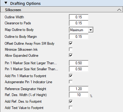
Drafting Options > Assembly - These settings are not saved to FPX file library

  • Outline Width - 0.12 (default)
  • Add Outline to Footprint - On (default)
  • Add Polarity Indication to Footprint - On (default)
    • This adds a 45-degree chamfer in the assembly outline near pin 1
  • Map Outline to Body
    • Minimum
    • Nominal
    • Maximum (default)
  • Ref. Des. Height Min. - 0.50 (default)
    • The Ref Des is scaled to fit inside the assembly outline
  • Ref. Des. Height Max. - 2.00 (default) 
    • This is the maximum assembly ref des height
    • Ref. Des. Width (% of Height) - 10% (default)
    • Add Ref. Des. to Footprint - On (default) 
    • Add Text Value to Footprint - Off (default)
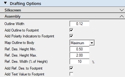
Drafting Options > Courtyard - These settings are not saved to FPX file library

  • Outline Width - 0.05 (default)
  • Add Outline to Footprint - On (default)
  • Expand Courtyard to Include Silkscreen - On (default)
  • Apply Courtyard Excess Option to Body - Yes (default)
    • Selecting No will turn off the courtyard excess
  • Apply Courtyard Excess Option to Pads - Yes (default)
    • Selecting No will turn off the courtyard excess
    • Selecting Ignore will turn off the pads
  • Contoured Outline - On (default)
    • Off = a rectangular courtyard
  • Minimum Courtyard Cut-in Gap - 5.00 (default)
    • This feature controls the courtyard cut-in between the pads
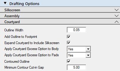
Drafting Options > Origin - These settings are not saved to FPX file library

  • Outline Width - 0.05 (default)
  • Crosshair Size - 0.70 (default)
  • Add Crosshair to Footprint - On (default)
  • Target Diameter - 0.50 (default)
  • Add Target to Footprint - On (default)
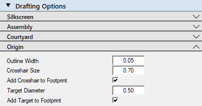
Drafting Options > Component and Terminal Outlines - These settings are not saved to FPX file library

  • Component Outline Width - 0.025 (default)
  • Add Component Outline to Footprint - On (default)
  • Terminal Outline Width - 0.025 (default)
  • Add Terminal Outlines to Footprint - On (default)
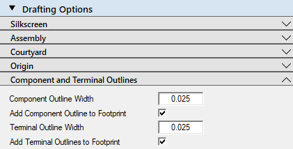
Footprint > Manufacturer's Dimensions - These dimensions are saved to the FPX file library

  • Use manufacturer's recommended dimensions - Off (default)
    • Selecting On turns on the manufacturer's dimension cells
      • G = pad to pad gap
      • X = pad length
      • Y = pad width
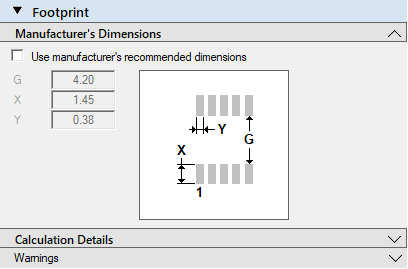
Footprint > Calculation Details - These settings are not saved to FPX file library

  • Component 
    • These are package dimensions
      • L = E
      • S = G
      • T = L
 
  • True Footprint
    • Zmax = G + X times 2
    • Gmin = G
    • Yref = Y

  • Terminal Protrusion Goals
    • Outer - Goal, Min, Max
    • Inner - Goal, Min, Max
    • Side - Goal, Min, Max
 
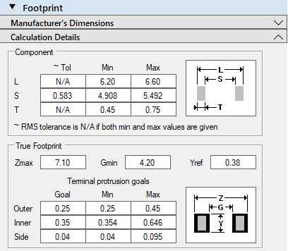
PCB Footprint Expert
The Footprint Expert will generate your footprints with accurate, consistent, reliable local and global calculator options to minimize chances of human error. Modify a setting, then batch-rebuild your entire library! The Footprint Expert helps you create flawless PCB designs much more efficiently!

Get your FREE Footprint Calculator or Footprint Expert Evaluation License:
Call:  847-557-2300
Stay connected - follow us! X - LinkedIn
Back to Top
Back to Top
 Post Reply Post Reply

Forum Jump Forum Permissions View Drop Down


This page was generated in 0.250 seconds.