
 |

|
TI DQN import not pretty |
Post Reply 
|
| Author | |
jameshead 
Expert User 
Joined: 20 Mar 2012 Location: Oxfordshire, UK Status: Offline Points: 576 |
 Post Options Post Options
 Thanks(1) Thanks(1)
 Quote Quote  Reply Reply
 Topic: TI DQN import not pretty Topic: TI DQN import not prettyPosted: 20 Mar 2014 at 4:42am |
|
I don't know immediately if this is something that Pulsonix has failed to convert correctly from the PADS ascii output created via FPX or if the PADS ascii output from FPX is not quite right.
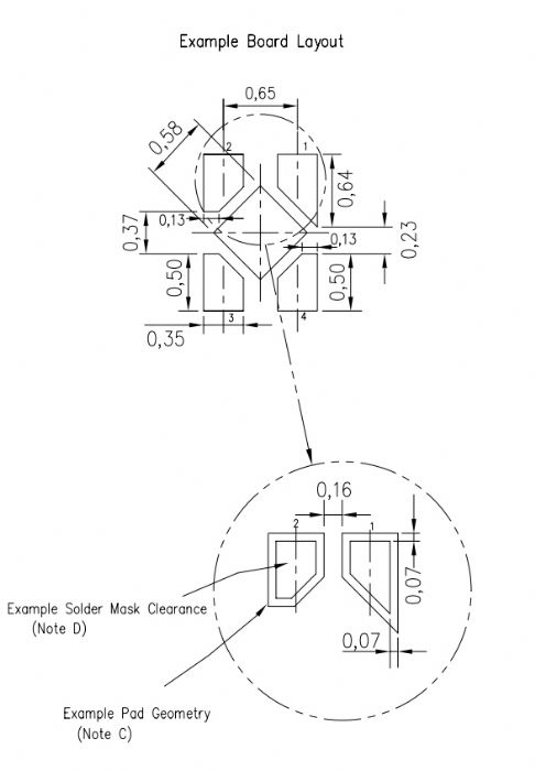
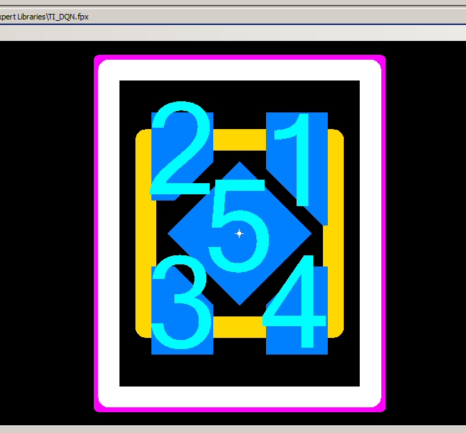
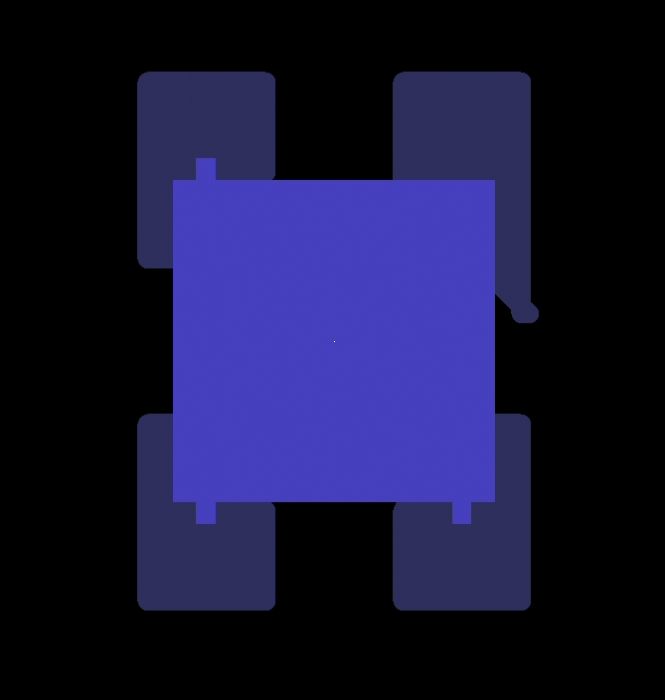
I had a go at creating the TI DQN footprint in the FP Designer.  TI datasheet here: http://www.ti.com/lit/ds/symlink/tlv71330p.pdf The footprint looked reasonable in FPX  The PADS ascii imported to Pulsonix with this result:  I was expecting the drawn copper areas with the small pads for the four corner pads because of the PADS limitations. I would normaly now create a pad style in Pusonix and make sure it matches up with the drawn corner pads. The centre pad has been replaced with a square of 0.82 mm side lengths though. To be honest I was expecting the PADS output to be a drawn copper diamond shape again with the small pad in the centre. Pulsonix supports a diamond pad shape though so I'd just substitute with this. I can't check importing the PADS ascii into PADS here though so I'm uploading all the relevant files. uploads/53/TI_DQN.fpx uploads/53/TI_DQN_PADS_ASCII.zip I'd generally try to use FPX then replace the pads in the imported-to-Pulsonix footprint with defined ones. |
|
 |
|
 |
|
jameshead 
Expert User 
Joined: 20 Mar 2012 Location: Oxfordshire, UK Status: Offline Points: 576 |
 Post Options Post Options
 Thanks(0) Thanks(0)
 Quote Quote  Reply Reply
 Posted: 20 Mar 2014 at 5:06am Posted: 20 Mar 2014 at 5:06am |
|
Just to clarify, the centre pad I would expect on a PADS output to be a small square with a drawn copper polygon for the "diamond" shape pad in the centre.
I pulsonix I would replace this with a pad, pad style being diamond 0.82 mm width, 0.82 mm length. I was surprised that the PADS asciii had the 0.82mm square pad style. Perhaps there's a rotation in the ascii that Pulsonix has failed to recognise, or is the PADS ascii output not correct? |
|
 |
|
jameshead 
Expert User 
Joined: 20 Mar 2012 Location: Oxfordshire, UK Status: Offline Points: 576 |
 Post Options Post Options
 Thanks(0) Thanks(0)
 Quote Quote  Reply Reply
 Posted: 20 Mar 2014 at 7:26am Posted: 20 Mar 2014 at 7:26am |
|
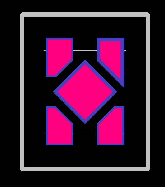
Here's the footprint done in Pulsonix with Pulsonix's user defined pad styles used.
 And a zip file with the Pulsonix format footprint in it. uploads/53/Texas_Instruments_DQN_in_Pulsonix_format.zip |
|
 |
|
chrisa_pcb 
Moderator Group 
Joined: 29 Jul 2012 Location: San Diego Status: Offline Points: 772 |
 Post Options Post Options
 Thanks(1) Thanks(1)
 Quote Quote  Reply Reply
 Posted: 20 Mar 2014 at 4:19pm Posted: 20 Mar 2014 at 4:19pm |
|
The center pin is created as a normal square pad with chamfers. The chamfers happen to be half the corner width. I am able to bring it into PADS without issue(excepting the bug below). Now, if you use a PADS output earlier than 9(which is where built-in chamfering of squares and rectangles was introduced), you should be able to generate it as a pad with associated copper, similar to how a thermal tab with chamfer/rounded corners is produced in all versions. Keep in mind, there is also a bug where pin 1 is generating a negative pad width. I've fixed this in the code, but to do it manually in the .d set its width and length in the .d to 0.05. Like this: PAD 0 5 N 0 |
|
 |
|
chrisa_pcb 
Moderator Group 
Joined: 29 Jul 2012 Location: San Diego Status: Offline Points: 772 |
 Post Options Post Options
 Thanks(1) Thanks(1)
 Quote Quote  Reply Reply
 Posted: 20 Mar 2014 at 5:10pm Posted: 20 Mar 2014 at 5:10pm |
|
I also went ahead and figured out why the pin 1 had the weird blob at the end and fixed it. This is how it now looks in PADS. We'll see about getting you a pre-release with these fixes.
|
|
 |
|
jameshead 
Expert User 
Joined: 20 Mar 2012 Location: Oxfordshire, UK Status: Offline Points: 576 |
 Post Options Post Options
 Thanks(0) Thanks(0)
 Quote Quote  Reply Reply
 Posted: 21 Mar 2014 at 1:25am Posted: 21 Mar 2014 at 1:25am |
|
Thanks,
I use the PADS ascii 9.3 format output since this has support for rounded rectangles which Pulsonix also recognises on the import. I tend to use the .asc output rather than the .d and .p output. |
|
 |
|
AGONZ67 
Advanced User 
Joined: 30 Mar 2012 Status: Offline Points: 119 |
 Post Options Post Options
 Thanks(0) Thanks(0)
 Quote Quote  Reply Reply
 Posted: 28 Mar 2014 at 9:41am Posted: 28 Mar 2014 at 9:41am |
|
I manually created this part a while back and used rectangle as the shape of the pad with equal width and length of 0.5mm. I set the orientation to 45 and it worked perfectly. The shape isn't a square with chamfers it is a square rotated 45 degrees.
|
|
 |
|
Post Reply 
|
|
| Tweet |
| Forum Jump | Forum Permissions  You cannot post new topics in this forum You cannot reply to topics in this forum You cannot delete your posts in this forum You cannot edit your posts in this forum You cannot create polls in this forum You cannot vote in polls in this forum |