

|
|
BGA With Staggered Pins |
Post Reply 
|
| Author | |
lalexman 
Expert User 
Joined: 30 Jul 2012 Status: Offline Points: 679 |
 Post Options Post Options
") Thanks(0) Thanks(0)
 Quote Reply Quote Reply
 Topic: BGA With Staggered Pins Topic: BGA With Staggered PinsPosted: 31 Mar 2015 at 7:08am |
|
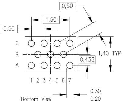
I am trying to create a Texas Instruments ZSU (R-uCSP-N11) that is a 3 by 7 matrix with missing every other pin. The software does not take into account the missing pins when using the pin to pin spacing rule and end up trimming the pads.
|
|
 |
|
|
|
|
Tom H
Admin Group 

Joined: 05 Jan 2012 Location: San Diego, CA Status: Offline Points: 5716 |
Post Options
Thanks(0)
Quote Reply
Posted: 31 Mar 2015 at 7:18am |
|
This package is a 5 minute FP Designer part. Please don't use the IPC Calculator to create non-standard footprints. http://www.ti.com/lit/ml/mubg002/mubg002.pdf
 |
|
|
|
|
lalexman
Expert User
Joined: 30 Jul 2012 Status: Offline Points: 679 |
Post Options
Thanks(0)
Quote Reply
Posted: 31 Mar 2015 at 7:22am |
|
Why do you consider it a non-standard part instead of the software not checking the clearance to a non existent pin ?
|
|
|
|
|
Tom H
Admin Group
Joined: 05 Jan 2012 Location: San Diego, CA Status: Offline Points: 5716 |
Post Options
Thanks(0)
Quote Reply
Posted: 31 Mar 2015 at 7:26am |
|
It's a non-standard part because the IPC calculator was not set up to handle staggered pin BGA's.
Can you please tell us what the TI Logical Part Number is and I will create it in less than 5 minutes and post it here so you can see the speed and power of FP Designer. I have a webcast at 8:00am PST so please hurry. |
|
|
|
|
lalexman
Expert User
Joined: 30 Jul 2012 Status: Offline Points: 679 |
Post Options
Thanks(0)
Quote Reply
Posted: 31 Mar 2015 at 7:32am |
|
I already created the part in the IPC calculator and fixed the clearance problem by setting the pad to pad clearance to zero. The only reason I suggest fixing it in the calculator is I created the part the first time and only noticed the pads were way too small when placing the part in pads. This is dangerous if you miss it.
|
|
|
|
|
lalexman
Expert User
Joined: 30 Jul 2012 Status: Offline Points: 679 |
Post Options
Thanks(0)
Quote Reply
Posted: 31 Mar 2015 at 1:31pm |
|
Did you ever see my last post ? |
|
|
|
|
Tom H
Admin Group
Joined: 05 Jan 2012 Location: San Diego, CA Status: Offline Points: 5716 |
Post Options
Thanks(0)
Quote Reply
Posted: 31 Mar 2015 at 2:23pm |
|
You can request "Staggered Row" BGA Calculator in Product Suggestions forum.
I built the part flawlessly in less than 5 minutes in FP Designer (less time than answering all these questions). I would have posted it here for free if you would have answered my request.
|
|
|
|
|
lalexman
Expert User
Joined: 30 Jul 2012 Status: Offline Points: 679 |
Post Options
Thanks(0)
Quote Reply
Posted: 31 Mar 2015 at 2:30pm |
|
Sorry Tom but I think you are missing the point. I can and did built this part as a 3 x 7 matrix bga and removed certain pins not with FP designer but with bga calculator. There is no need to request a "Staggered ROW" bga calculator as you can use the existing bga calculator. The problem I ran into is The software does not take into account the missing pins when using the pin to pin spacing rule and ends up trimming the pads and does not need to. The only reason I suggest fixing it in the calculator is I created the part the first time and only noticed the pads were way too small when placing the part in pads. This is dangerous if you miss it.
I guess I should have posted this in as a bug ? |
|
|
|
|
Post Reply
|
|
| Tweet |
| Forum Jump | Forum Permissions You cannot post new topics in this forum You cannot reply to topics in this forum You cannot delete your posts in this forum You cannot edit your posts in this forum You cannot create polls in this forum You cannot vote in polls in this forum |


 Topic Options