

|
|
Output for Terminals? |
Post Reply 
|
| Author | |
rickdehart 
Advanced User 

Joined: 18 Apr 2012 Location: Austin, TX Status: Offline Points: 184 |
 Post Options Post Options
") Thanks(0) Thanks(0)
 Quote Reply Quote Reply
 Topic: Output for Terminals? Topic: Output for Terminals?Posted: 25 Oct 2012 at 11:48am |
|
Is the actual pin included with the 3D Model output?
|
|
 |
|

|
|
|
|
|
rickdehart
Advanced User
Joined: 18 Apr 2012 Location: Austin, TX Status: Offline Points: 184 |
Post Options
Thanks(0)
Quote Reply
Posted: 25 Oct 2012 at 12:42pm |
|
I am reffering to the CAD output from Footprint Expert. The 3D Model outline is an output, but does not seem to include the terminal. I would like to be able to get the Model Outline and Termninals on one layer of CAD output. 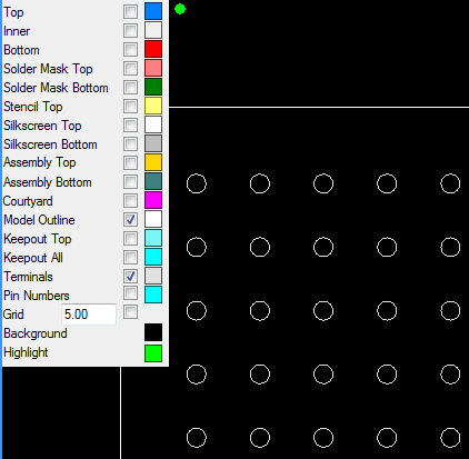 |
|
|
|
|
Tom H
Admin Group 

Joined: 05 Jan 2012 Location: San Diego, CA Status: Offline Points: 6072 |
Post Options
Thanks(0)
Quote Reply
Posted: 25 Oct 2012 at 12:48pm |
|
The 3D Model outline is used for IDF export and only creates a polygon with Height. No leads or pins.
|
|
|
|
|
rickdehart
Advanced User
Joined: 18 Apr 2012 Location: Austin, TX Status: Offline Points: 184 |
Post Options
Thanks(0)
Quote Reply
Posted: 25 Oct 2012 at 1:39pm |
|
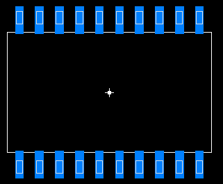
Would it be possible on future versions to include Terminals as one of the layers to export to cad? This way I can choose which layer to put it on. It would help us to visualize the Body/Pins on top of the Land Pattern during Layout and DFM checks.
We would like to see this during DFM checks:
 |
|
|
|
|
Tom H
Admin Group
Joined: 05 Jan 2012 Location: San Diego, CA Status: Offline Points: 6072 |
Post Options
Thanks(0)
Quote Reply
Posted: 25 Oct 2012 at 1:42pm |
|
The big issue is the CAD tool layer. We need to add a major feature that allows users to define additional layers for drafting items.
|
|
|
|
|
Post Reply
|
|
| Tweet |
| Forum Jump | Forum Permissions You cannot post new topics in this forum You cannot reply to topics in this forum You cannot delete your posts in this forum You cannot edit your posts in this forum You cannot create polls in this forum You cannot vote in polls in this forum |


 Topic Options