

|
|
Molded Body 3D STEP Model Issue |
Post Reply 
|
| Author | |
rrix 
Active User 
Joined: 10 Jan 2018 Status: Offline Points: 34 |
 Post Options Post Options
") Thanks(0) Thanks(0)
 Quote Reply Quote Reply
 Topic: Molded Body 3D STEP Model Issue Topic: Molded Body 3D STEP Model IssuePosted: 17 Aug 2023 at 11:08am |
|
When I look at a STEP file for a molded body exported from Footprint Expert, I'm seeing issues with both pins on the part.
It looks like the top part of the pins can't properly solidify. I'm seeing this anomaly in OrCAD and E-Drawings. If I export a STEP file with just this one part on the board in OrCAD, it fails when trying to import into CREO (MCAD software). 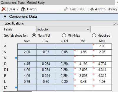 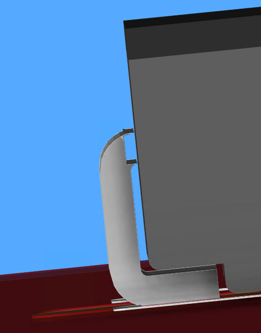 |
|
 |
|

|
|
|
|
|
Tom H
Admin Group 

Joined: 05 Jan 2012 Location: San Diego, CA Status: Offline Points: 6070 |
Post Options
Thanks(0)
Quote Reply
Posted: 17 Aug 2023 at 11:26am |
|
The master 3D STEP model was designed for the JEDEC DO-214 package.
Major Note: The "D" dimension must be at least (minimum) 0.80 mm larger than the "D1" dimension. This allows the 0.20 mm thick terminal lead to exit the package and have a bend radius. There are some Molded Body packages where the terminal lead is against the package body. This is a non-standard package and it's not recognized by JEDEC, EIA or IPC. You need to use the FP Designer module to create these non-standard footprints using the mfr. recommended pattern. And get the 3D STEP model from the component mfr.
 |
|
|
|
|
rrix
Active User
Joined: 10 Jan 2018 Status: Offline Points: 34 |
Post Options
Thanks(0)
Quote Reply
Posted: 17 Aug 2023 at 11:59am |
|
Understood. Request you consider this as a possible enhancement for the future. I know the manufacturer's don't always follow the standards, but it's what we have to deal with (and they don't always have a STEP file and then we would have to generate one manually). Also, would it be possible to provide some indication that the 0.8mm requirement was being violated? That way I would know there's an issue right away. I do a quick visual check, but don't normally zoom in to check all the geometry of the STEP file. I only found this since my MCAD team was complaining about it.
Thanks for the reply. I'll try to keep this in mind when creating a molded body part.
|
|
|
|
|
Jeff.M
Admin Group

Joined: 16 May 2012 Location: San Diego Status: Offline Points: 500 |
Post Options
Thanks(0)
Quote Reply
Posted: 27 Sep 2023 at 10:05am |
|
Added an error provider to flag any D1 value is greater than D minus twice the minimum terminal thickness of 0.3mm (D - D1 must be greater than 0.60 mm).
|
|
|
|
|
Tom H
Admin Group
Joined: 05 Jan 2012 Location: San Diego, CA Status: Offline Points: 6070 |
Post Options
Thanks(0)
Quote Reply
Posted: 27 Sep 2023 at 11:04am |
|
Note: Footprint Expert 3D STEP models are not 100% compatible with CREO (MCAD software).
|
|
|
|
|
Post Reply
|
|
| Tweet |
| Forum Jump | Forum Permissions You cannot post new topics in this forum You cannot reply to topics in this forum You cannot delete your posts in this forum You cannot edit your posts in this forum You cannot create polls in this forum You cannot vote in polls in this forum |


 Topic Options