|
|
Outline Dimensions Are Not Shown? |
Post Reply 
|
| Author | |
Matthew Lamkin 
Advanced User 
Joined: 02 Oct 2012 Status: Offline Points: 284 |
 Post Options Post Options
") Thanks(0) Thanks(0)
 Quote Reply Quote Reply
 Topic: Outline Dimensions Are Not Shown? Topic: Outline Dimensions Are Not Shown?Posted: 16 May 2014 at 12:46am |
|
Hi, using the tool I cannot see anywhere that shows the dimensions of the placement courtyard?
(Or the silkscreen/assembly outlines etc.) ISTR that these were shown in the LPWizard. Given that the placement courtyard is a critical shape that all components should have why are these dimensions not shown? It makes it impossible to check a component is correct to this tools output when in the native CAD system. Why is this? |
|
 |
|

|
|
|
|
|
Tom H
Admin Group 

Joined: 05 Jan 2012 Location: San Diego, CA Status: Offline Points: 6063 |
Post Options
Thanks(0)
Quote Reply
Posted: 16 May 2014 at 6:47am |
|
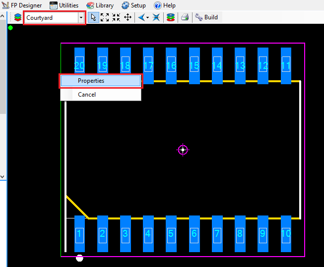
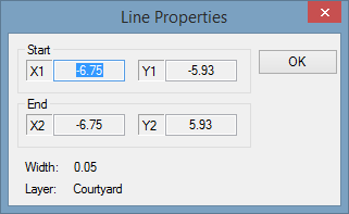
In the Calculator window, Right Mouse Button click and there are options for Pads, Shapes, Lines, Text, etc. select Lines or Shapes.
Then drop down the Layer you want to select. In this case it would be "Courtyard". Then Left Mouse Button and select the courtyard and Right Mouse Button select "Properties". You can do this with any component family.
|
|
|
|
|
Matthew Lamkin
Advanced User
Joined: 02 Oct 2012 Status: Offline Points: 284 |
Post Options
Thanks(0)
Quote Reply
Posted: 16 May 2014 at 9:03am |
|
I would say that's not very user friendly.
Neither can it be printed out when someone needs to do some documentation to backup their parts info. An example in case - if someone else makes a part using the wizard and then adds it to the PCB CAD library, someone else checks the part and when trying to check the footprint which has been created by the tool - they cannot unless they enter all the information into the tool again. So when creating a component, the creator could print to PDF all dimensions etc, except this does not include the outline dimensions like the old tool did. If the pad dimensions are output then the outline dimensions should too. I have personally had this issue recently so the LPWizard was used to create the components instead as it produces a superior printed output. This sort of situation is applicable to many large companies, MOD compliant, aerospace ones etc where they tend to keep lots of information so it can be checked and cross checked before a board is sent where it must not fail. (not that this is likely to make it fail - but you get the point.) |
|
|
|
|
Post Reply
|
|
| Tweet |
| Forum Jump | Forum Permissions You cannot post new topics in this forum You cannot reply to topics in this forum You cannot delete your posts in this forum You cannot edit your posts in this forum You cannot create polls in this forum You cannot vote in polls in this forum |


 Topic Options