

|
|
Courtyard Excess Not Updating |
Post Reply 
|
| Author | |
ChrisChris 
Advanced User 
Joined: 03 Nov 2021 Status: Offline Points: 92 |
 Post Options Post Options
") Thanks(0) Thanks(0)
 Quote Reply Quote Reply
 Topic: Courtyard Excess Not Updating Topic: Courtyard Excess Not UpdatingPosted: 12 Feb 2022 at 4:29pm |
|
Hello,
I am trying to apply the MFC recommended land for a simple 0402 cap and also customize the Courtyard Excesses. Their default values are 0.15mm but for this case I want them to be 0.19mm. "Before" screenshot hereafter. After entering the case dimensions I 1) apply the MFC recommended land, then 2) modify the Courtyard Excesses, then 3) Calculate. I see the Courtyard Excess correctly update in the Footprint window. I then click update the selected row to update a previously existing version of the same part. 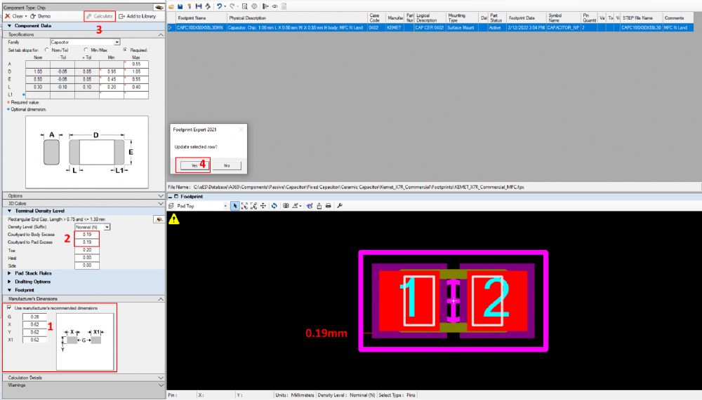 The "After" screenshot after I double-click on the Row arrow in the Library window to re-load the footprint. Note, right clicking the Library row and selecting View --> Selected Footprint produces the same result. 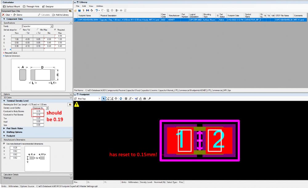 The Courtyard Excesses are incorrect (have been reset to the 0.15mm default). The Footprint window has also reset to the small excess value. *scratching head* Thanks in advance for you help. Chris
|
|
 |
|

|
|
|
|
|
Tom H
Admin Group 

Joined: 05 Jan 2012 Location: San Diego, CA Status: Offline Points: 6088 |
Post Options
Thanks(0)
Quote Reply
Posted: 12 Feb 2022 at 5:50pm |
|
The Library Editor FPX file does not save any Options.
You need to change your Global Options. Changing Local Options on the fly is strictly used for creating a unique CAD library part. There are Option file instructions on your computer in this folder: C:\Program Files (x86)\PCB Libraries\Footprint Expert 2022\Documents Create your Master Options - "Tools > Options > File > Save As > Your Master Option file" Then edit your Terminal Courtyard Settings. If you need help, we can do a webcast Q & A. |
|
|
|
|
ChrisChris
Advanced User
Joined: 03 Nov 2021 Status: Offline Points: 92 |
Post Options
Thanks(0)
Quote Reply
Posted: 12 Feb 2022 at 7:55pm |
|
Hi Tom, When you say create a unique CAD library part do you mean using the Designer feature? If all of these items in the Options window on the lower left do not impact the saved footprint, why does the tool allow me to modify them and then update the rendering according to my changes when I click Calculate? That is terribly confusing, especially when I find out (incidentally) that the changes are not saved. I already have a Master Options file and the 0.15mm default is good for my default, but I have a bunch of parts that have different minimum courtyard excesses. How am I supposed to handle this? If I'm following you correctly, it sounds like for each footprint I need to change my Master Options, design the footprint, then build the part to export for Altium with the Courtyard Excess applied. Any FPX I save will not have this information in it, so I need to manually maintain a spreadsheet lookup that tells me what Courtyard Excesses I need to apply on a by-footprint basis in case I ever need to rebuild one or more of them again. Is this correct? I hope not. Thanks, Chris |
|
|
|
|
Tom H
Admin Group
Joined: 05 Jan 2012 Location: San Diego, CA Status: Offline Points: 6088 |
Post Options
Thanks(0)
Quote Reply
Posted: 13 Feb 2022 at 9:32am |
|
A unique standard footprint may have custom Toe, Heel, Side goals, drafting outline widths, courtyard excess, pad shape, etc. you cannot save this data to FPX unless you create it in FP Designer.
I'm referring to changing the Option values locally in the Calculator and immediately outputting to a CAD tool. There are different Pad and Body Courtyard Excess for every Terminal type and pitch. i.e.: different Courtyard settings for chip packages 01005, 0201, 0402, 0603, 0805, 1206, etc. There are different Courtyard Excess settings for various pin pitch Gull Wing leads for 0.50, 0.65, 0.80, 1.00, 1.27 pin pitches. And we break it down by component family too, SOT, SOP, DPAK and then the various pin pitches. But if you want a custom courtyard excess for each footprint and save those settings to FPX, then move or create in FP Designer. Again, you may need a Q & A webcast to get the full understanding of Footprint Expert and all the features. |
|
|
|
|
ChrisChris
Advanced User
Joined: 03 Nov 2021 Status: Offline Points: 92 |
Post Options
Thanks(0)
Quote Reply
Posted: 14 Feb 2022 at 9:21am |
|
OK, I will see how to create them in FP Designer.
Thanks Tom!
|
|
|
|
|
Post Reply
|
|
| Tweet |
| Forum Jump | Forum Permissions You cannot post new topics in this forum You cannot reply to topics in this forum You cannot delete your posts in this forum You cannot edit your posts in this forum You cannot create polls in this forum You cannot vote in polls in this forum |


 Topic Options