

|
|
The '+' Polarity Symbol Dimensions |
Post Reply 
|
| Author | |
m.elsayed 
Committee 
Joined: 22 Sep 2016 Status: Offline Points: 269 |
 Post Options Post Options
") Thanks(0) Thanks(0)
 Quote Reply Quote Reply
 Topic: The '+' Polarity Symbol Dimensions Topic: The '+' Polarity Symbol DimensionsPosted: 14 Sep 2025 at 6:58am |
|
I have '+' polarity marker in Silkscreen and Assembly layers with same dimension as line width = 0.05 mm and size = 1.016 mm
However, when open in Altium Designer the '+' symbol has different dimension values. Footprint Expert: 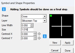 Altium Assembly:  Silkscreen: 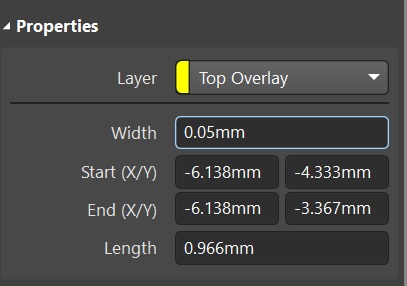 |
|
 |
|

|
|
|
|
|
tgrodnicki
Advanced User 
Joined: 30 Sep 2014 Status: Offline Points: 141 |
Post Options
Thanks(1)
Quote Reply
Posted: 14 Sep 2025 at 11:22pm |
|
Footprint Expert reports the length of the lines forming the cross as the maximum value.
Most CAD programs do not account for round ends when reporting the length of the lines. If you subtract the width (0.050) from the length reported by Footprint Expert (1.016), you get the result reported by Altium Designer (0.966).
|
|
|
|
|
m.elsayed
Committee
Joined: 22 Sep 2016 Status: Offline Points: 269 |
Post Options
Thanks(0)
Quote Reply
Posted: 15 Sep 2025 at 5:51am |
|
But also, I found in line width changed to 0.254 mm other layer assembly.
However, I changed the line width to 0.05 mm. |
|
|
|
|
Tom H
Admin Group 

Joined: 05 Jan 2012 Location: San Diego, CA Status: Offline Points: 6075 |
Post Options
Thanks(0)
Quote Reply
Posted: 15 Sep 2025 at 3:25pm |
|
I created a Silkscreen Plus + symbol in Footprint Expert 1.00 mm X 0.15 mm line width.
Here is the Footprint Expert Symbol dialog box: 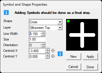 I translated the footprint to Altium and here are the Plus Symbol dimensions. 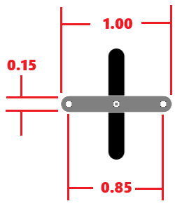 Here is the Altium Properties for the Polarity Marker: 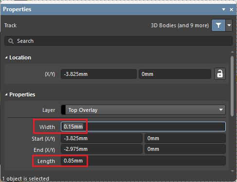 It seems to be working 100% correct. Can you confirm that the issue you reported is working correctly? |
|
|
|
|
m.elsayed
Committee
Joined: 22 Sep 2016 Status: Offline Points: 269 |
Post Options
Thanks(0)
Quote Reply
Posted: 16 Sep 2025 at 2:20am |
|
Thanks Tom, for your great support
I have get your point in length, but for line width i notice below:- 1-Silkscreen however i have selected value line width =0.05 mm and select Apply & Done, a 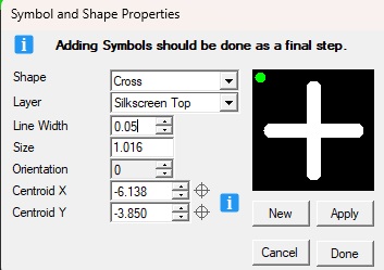 and then checked found it 0.15 mm (PCb tool) 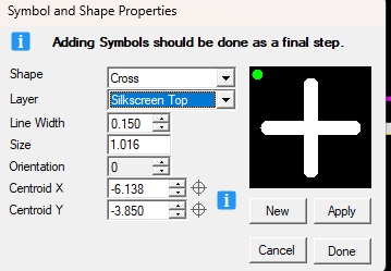 2-Assembly however i select 0.05 mm in line width 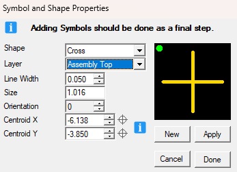 i found it in altium as 0.025 mm 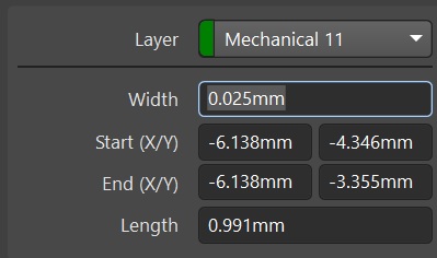 please can check and have explanation what happen and causes for this
|
|
|
|
|
tgrodnicki
Advanced User
Joined: 30 Sep 2014 Status: Offline Points: 141 |
Post Options
Thanks(1)
Quote Reply
Posted: 16 Sep 2025 at 11:43pm |
|
In 25.10, 9/16/2025 prelease version the bug with Symbol and Shape Properties window has been fixed.
I don't use Altium, so I can't comment on the translator's accuracy.
|
|
|
|
|
m.elsayed
Committee
Joined: 22 Sep 2016 Status: Offline Points: 269 |
Post Options
Thanks(1)
Quote Reply
Posted: 17 Sep 2025 at 1:33am |
|
uploads/11979/te_part_2025-09-17_01-30-36.fpx
please check fpx file and .pcblib file also
|
|
|
|
|
Tom H
Admin Group
Joined: 05 Jan 2012 Location: San Diego, CA Status: Offline Points: 6075 |
Post Options
Thanks(0)
Quote Reply
Posted: 17 Sep 2025 at 7:57am |
|
The Symbol and Shape feature was fixed in the V25.10 pre-release dated 9/16/25.
Also, the new Min/Max Assembly Polarity Dot was added to Options. The Chamfer Polarity is the default setting but users can now switch to an Assembly Dot. |
|
|
|
|
m.elsayed
Committee
Joined: 22 Sep 2016 Status: Offline Points: 269 |
Post Options
Thanks(0)
Quote Reply
Posted: 14 Oct 2025 at 12:39pm |
|
Thanks tom it's ok
|
|
|
|
|
Post Reply
|
|
| Tweet |
| Forum Jump | Forum Permissions You cannot post new topics in this forum You cannot reply to topics in this forum You cannot delete your posts in this forum You cannot edit your posts in this forum You cannot create polls in this forum You cannot vote in polls in this forum |


 Topic Options