GPS-PA6B
Printed From: PCB Libraries Forum
Category: PCB Footprint Expert
Forum Name: Questions & Answers
Forum Description: issues and technical support
URL: https://www.PCBLibraries.com/forum/forum_posts.asp?TID=738
Printed Date: 24 Jul 2026 at 6:01pm
Topic: GPS-PA6B
Posted By: hakaday
Subject: GPS-PA6B
Date Posted: 08 Dec 2012 at 2:39am
|
Hi all I haven't done any PCB related work for about 10 years. I would like to layout a GPS board based on the PA6B GPS module from GTop and do it once with the correct footprints. How does one define a custom component or which footprint should one use to start a footprint for this device. I'm using the freeware version for the moment. The datasheet for the device is located here: http://www.gtop-tech.com/en/product/GPS_Modules_PA6B.html" rel="nofollow - http://www.gtop-tech.com/en/product/GPS_Modules_PA6B.html Thanks for your help. |
Replies:
Posted By: Tom H
Date Posted: 08 Dec 2012 at 8:13am
|
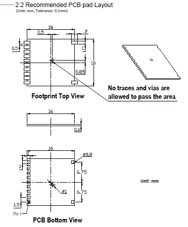
You need a little more information than the datasheet provides. You need the physical component dimensions and/or the manufacturer recommended footprint dimensions. |
Posted By: hakaday
Date Posted: 08 Dec 2012 at 9:12am
|
Thanks for the reply Tom. The linked document is unfortunately all I have to work with. But I believe all the relevant data is in the datasheet. Steven |
Posted By: Tom H
Date Posted: 08 Dec 2012 at 9:18am
|
Not enough data to create the PCB library part. |
Posted By: hakaday
Date Posted: 08 Dec 2012 at 9:49am
|
Posted By: Tom H
Date Posted: 08 Dec 2012 at 10:40am
|
Using the current PCB Footprint Expert, I built this library part in less than 2 minutes using the component manufacturer's recommended solder pattern. First I inserted the component dimensions and removed the deleted pins - 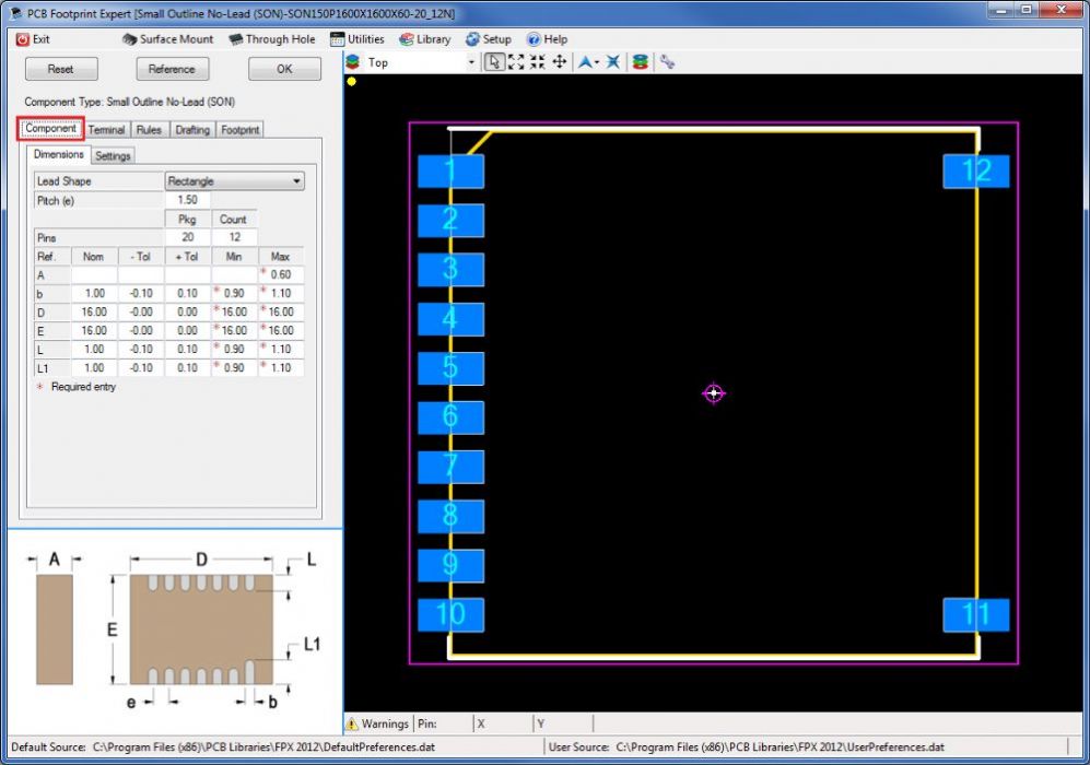 Then I selected the "Footprint" tab and inserted the component manufacturer's recommended solder pattern dimensions - 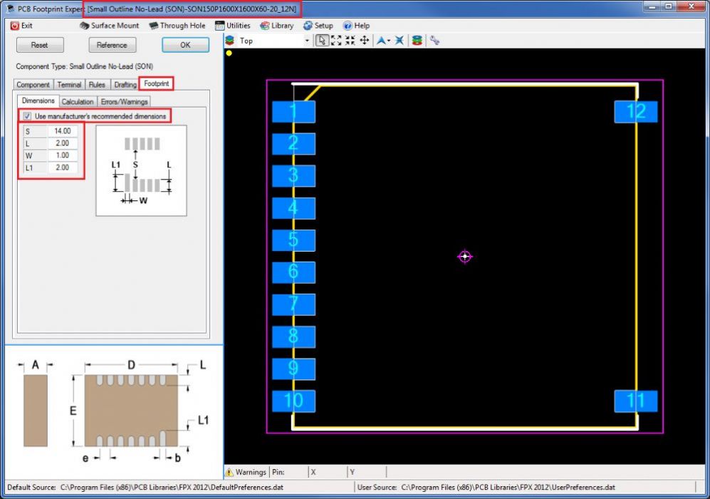 Then I selected the CAD tool of my choice and select the "Create" button - Bam! 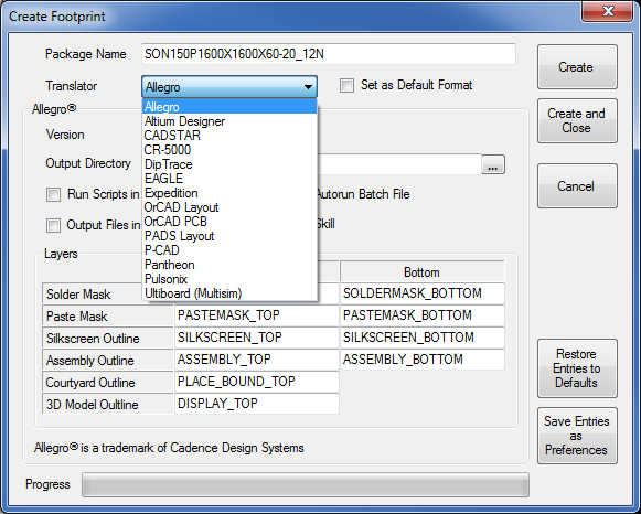 |
Posted By: hakaday
Date Posted: 08 Dec 2012 at 11:05am
|
Thanks Tom Part of the problem was, I did not know which component to use the start the definition. The other problem that I had (have) is deletion of the pins. (I will follow the tutorial again.) I also tried to create the hole for the antenna which did not work to well. I will follow your example. Your help is much appreciated. |
Posted By: Tom H
Date Posted: 08 Dec 2012 at 11:35am
| I used the SON (Small Outline No-lead) component family because it has the "Delete Pin" feature to remove the missing pins. |