Terminal Option Settings for SOT Devices
Printed From: PCB Libraries Forum
Category: PCB Footprint Expert
Forum Name: Questions & Answers
Forum Description: issues and technical support
URL: https://www.PCBLibraries.com/forum/forum_posts.asp?TID=3131
Printed Date: 24 Jul 2026 at 6:01pm
Topic: Terminal Option Settings for SOT Devices
Posted By: caclark
Subject: Terminal Option Settings for SOT Devices
Date Posted: 06 Jun 2022 at 11:51am
|
My issue is that I am getting huge courtyard settings on all my SOT devices. I thought I had something set wrong. I looked at the terminal settings for "Gullwing, SOT" and they are set as I want them (screenshot below). Then I really looked at the individual setting for one of the devices. That is when I noticed that the Terminal Density is being pulled from "Outward L Lead...". So which setting should this be pulling from "Gullwing, SOT" or "Outward L Lead..."? I thought these SOT's settings were split off long ago due to SOT packages often being quite small, but other "Outwards L" devices often be quite large. As a result it was way to hard to find common ground that would work for both very small and very large devices. 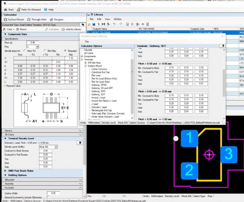 |
Replies:
Posted By: Tom H
Date Posted: 06 Jun 2022 at 12:03pm
|
You should update to V2022.08. Can you share your Option .opt file and your FPX file so we can reproduce? We tried to duplicate this issue using your screenshot but cannot reproduce. Thanks ------------- Stay connected - follow us! https://twitter.com/PCBLibraries" rel="nofollow - X - http://www.linkedin.com/company/pcb-libraries-inc-/" rel="nofollow - LinkedIn |
Posted By: caclark
Date Posted: 06 Jun 2022 at 12:56pm
|
Please see attached zip file uploads/1152/PCB_Lib_requested_files.zip" rel="nofollow - uploads/1152/PCB_Lib_requested_files.zip
|
Posted By: caclark
Date Posted: 06 Jun 2022 at 12:58pm
| Sorry, forgot to add this to the above. I tried it in both -07 and -08. Just so happens I captured the screen from -07 |
Posted By: Tom H
Date Posted: 06 Jun 2022 at 2:12pm
|
The issue is that the terminal lead on some gull wing type packages comes straight out of the side and straight down or the terminal is bent inwards. Terminals the go straight down or bend inwards are defined as "Outward L Lead" and only affect SOP, SOD and SOT packages. Go to "Tools > Options > Terminals > Surface Mount > Outward L Lead" and change all the courtyard excess values there and it will fix the problem. Here is what an Outward L Lead package looks like: 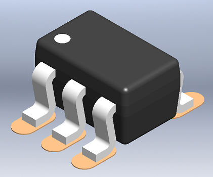 ------------- Stay connected - follow us! https://twitter.com/PCBLibraries" rel="nofollow - X - http://www.linkedin.com/company/pcb-libraries-inc-/" rel="nofollow - LinkedIn |
Posted By: caclark
Date Posted: 07 Jun 2022 at 3:39am
|
So then why is there a terminal group for "Gullwing SOT"? I often have the exact same device from several vendors, yes some have the leads defined to go inwards or straight down. Then others have the true "GullWing" shape to the leads. Often the only variable is the lead thickness which then determines if there is room to "Gullwing" the leads or allowes them to go straight down. I personally would rather have them defined seperatly. Some of those SOP packages are huge compared to the size of most SOT packages, though they share pitch spacing. Comes down to having to choose between the needs of the small SOT package courtyard spacing or their often times much larger brother courtyard spacing, as they are often more likely in need of re-work/touchup.
|
Posted By: Tom H
Date Posted: 07 Jun 2022 at 8:22am
|
The industry produces microminiature SOP packages mow. Most of them are big. The Outward L Lead has a small Heel and the Gullwing has a large Heel. Here is a normal Gullwing SOT: 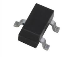 ------------- Stay connected - follow us! https://twitter.com/PCBLibraries" rel="nofollow - X - http://www.linkedin.com/company/pcb-libraries-inc-/" rel="nofollow - LinkedIn |