FP Designer Not Exporting Terminal Outlines
Printed From: PCB Libraries Forum
Category: PCB Footprint Expert
Forum Name: Questions & Answers
Forum Description: issues and technical support
URL: https://www.PCBLibraries.com/forum/forum_posts.asp?TID=3049
Printed Date: 24 Jul 2026 at 9:08pm
Topic: FP Designer Not Exporting Terminal Outlines
Posted By: ChrisChris
Subject: FP Designer Not Exporting Terminal Outlines
Date Posted: 14 Feb 2022 at 7:38pm
|
Hi Tom, I've just grown to presume you will be the one who answers this.  I've performed an A/B using the SMT Calculator and FP Designer for the 0402 cap footprint I posted about the other day. I believe I have everything set up correctly with the Courtyard Excess set to 0.15mm for the SMT Calculator version and 0.19mm for the FP Designer version. Everything looks aligned and identical except that the FP Designer footprint is not showing the terminal outlines even though I have them checked... 0402 footprint with 0.15mm Courtyard Excess created using SMT Calculator... 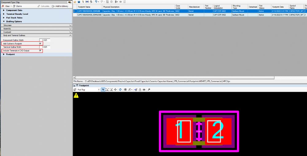 0402 footprint with 0,19mm Courtyard Excess created using FP Designer... 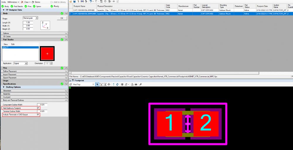 Any idea what I may be doing wrong here? Thanks! Chris
|
Replies:
Posted By: Tom H
Date Posted: 14 Feb 2022 at 8:09pm
|
Terminal outlines require dimensions. Those dimensions are in the Calculator, not FP Designer. If this is a simple 0402 why can’t you get the results you want in the Calculator using Master Options? ------------- Stay connected - follow us! https://twitter.com/PCBLibraries" rel="nofollow - X - http://www.linkedin.com/company/pcb-libraries-inc-/" rel="nofollow - LinkedIn |
Posted By: ChrisChris
Date Posted: 14 Feb 2022 at 8:14pm
| Per my other topic I need to create a bunch of 0402s with different Courtyard Excesses. So I need to use FP Designer. I guess I can't specify the terminals in FP Designer. Not a big deal. |