BGA Pad Size
Printed From: PCB Libraries Forum
Category: PCB Footprint Expert
Forum Name: Questions & Answers
Forum Description: issues and technical support
URL: https://www.PCBLibraries.com/forum/forum_posts.asp?TID=2607
Printed Date: 24 Jul 2026 at 6:20pm
Topic: BGA Pad Size
Posted By: 5not4
Subject: BGA Pad Size
Date Posted: 27 Feb 2020 at 8:54am
|
Tom. Can you explain how the tool calculates the footprint pad size for BGA's? Looking through IPC-7351B there are many explanations that seem to point to different sizes than the tool creates. Also, most manufactures suggest the footprint pad size should match the interposer pad size and I have yet to see the calculators create an equal pad size. Roy. |
Replies:
Posted By: Tom H
Date Posted: 27 Feb 2020 at 11:31am
|
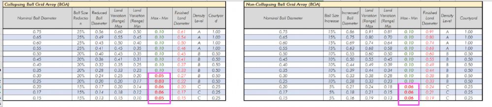
The IPC mathematical model uses this table to calculate BGA pad stacks, but the Library Expert Preferences allows the User to change the values to whatever works best for you. IPC uses different reduction values for various ball sizes and the Maximum Material Condition of the Land Variation.  ------------- Stay connected - follow us! https://twitter.com/PCBLibraries" rel="nofollow - X - http://www.linkedin.com/company/pcb-libraries-inc-/" rel="nofollow - LinkedIn |
Posted By: 5not4
Date Posted: 27 Feb 2020 at 12:03pm
|
Thanks Tom. I have an issue with that chart from IPC - it doesn't take into account devices with less than 1.0mm pitch which (according to IPC) requires 10% reduction. 14.2.4 Attachment Site Planning The attachment site or land pattern geometry recommended for BGA devices is round with the diameter adjusted to meet contact pitch and size variation. The diameter of the land should be no larger than the diameter of the land at the package interface and is typically 20% smaller than the normal diameter specified for the ball contact for pitches greater than 1.0 mm and 10% smaller for pitches less than 1.0 mm. Refer to the manufacturer specification before finalizing land pattern array and geometry. |
Posted By: Tom H
Date Posted: 27 Feb 2020 at 1:01pm
|
IPC-7351B Paragraph 14.2.4 seems to contradict everything else. Here are several things about BGA's that every PCB designer needs to know. 1. Once the pin pitch is 0.50 or lower, the normal dog-bone via fanout cannot be used. 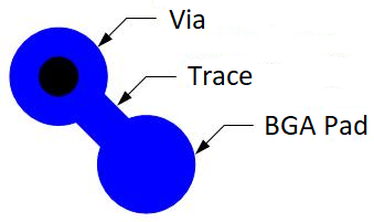 2. The BGA Ball should collapse around the pad.  3. Most 0.50 mm pitch BGA balls are not collapsible. The pad size must be made larger to accommodate via-in-pad technology and have an adequate annular ring for fabrication.  4. Most via-in-pad sizes are 0.15 mm and today's fabrication technology can drill through the board. Unlike 10 years ago when 0.15 mm vias had to be blind vias and required mass lamination. This was and is expensive. The via-in-pad must be plugged, plated over and planarized flat. Any dimple will trap air and cause Ball Voiding.  ------------- Stay connected - follow us! https://twitter.com/PCBLibraries" rel="nofollow - X - http://www.linkedin.com/company/pcb-libraries-inc-/" rel="nofollow - LinkedIn |
Posted By: stanleycayochok
Date Posted: 22 Mar 2021 at 1:08am
|
Hi Tom, I've noticed that the Min and Max Land variation range has no pattern from 0.3mm down to 0.15mm nominal ball diameter. The values are 0.05mm, 0.03mm and 0.06mm for the collapsing BGA. Library Expert seems to standardize it for the Non Collapsing BGA at 0.06mm for 0.20 to 0.17 nominal ball diameter. My question is what would be the Max - Min used for nom. balls that are not in the table for collapsing BGA. Example a 0.26mm nominal ball diameter or a 0.33mm nominal ball diameter. Would it be OK to set the Max- Min to a single value like 0.06mm for collapsing BGA balls of 0.30mm to 0.15mm nominal ball diameter?
 |
Posted By: Tom H
Date Posted: 22 Mar 2021 at 2:10pm
|
Non-collapsing BGA balls are intended for fine pitch parts where a normal dog-bone via fanout cannot be achieved and you must use via-in-pad technology for this trace routing solution. Non-collapsing BGA's have larger pads to accommodate via-in-pad and establish an adequate annular ring. The BGA ball does not collapse around the edge of the pad like a collapsing ball does. Rather, the solder mask is usually 1:1 scale of the pad size or even a solder mask defined pad to allow solder over the pad edge. This technique helps secure the pad to the prepreg. When the pad size gets too small, the assembly might be compromised in drop tests where the solder joint does not break but the pad to prepreg becomes detached, creating an open connection and then failure. Make your min/max land variation decision with this information. ------------- Stay connected - follow us! https://twitter.com/PCBLibraries" rel="nofollow - X - http://www.linkedin.com/company/pcb-libraries-inc-/" rel="nofollow - LinkedIn |
Posted By: stanleycayochok
Date Posted: 30 Mar 2021 at 10:35pm
| Thanks Tom. |
Posted By: flatronics
Date Posted: 22 Jun 2022 at 9:11pm
|
Hi Tom, Is the Nominal Land Diameter and Reduced Ball diameter from the above tables the same? What will be the actual Land Diameter from the table to be used in our pad stack? Will it be the Nominal Land Diameter/Reduced Ball Diameter or the Finished Land Diameter? I'd really appreciate your response. Thank you very much in advanced.
|
Posted By: Tom H
Date Posted: 23 Jun 2022 at 7:52am
Here is the BGA Pad Size Reduction table for Collapsing Balls:  Here is the BGA Pad Size Reduction table for Non-Collapsing Balls:  ------------- Stay connected - follow us! https://twitter.com/PCBLibraries" rel="nofollow - X - http://www.linkedin.com/company/pcb-libraries-inc-/" rel="nofollow - LinkedIn |