Shrouded Header - Save User Rotation in FPX
Printed From: PCB Libraries Forum
Category: PCB Footprint Expert
Forum Name: Questions & Answers
Forum Description: issues and technical support
URL: https://www.PCBLibraries.com/forum/forum_posts.asp?TID=1681
Printed Date: 06 Jun 2026 at 1:27am
Topic: Shrouded Header - Save User Rotation in FPX
Posted By: DaveCowl
Subject: Shrouded Header - Save User Rotation in FPX
Date Posted: 18 May 2015 at 5:04pm
|
I have created a shrouded header which has a name that is too long for Allegro but also has to be rotated before creation. PCB Libraries wants to draw the part like this (even with the Pin 1 Orientation set to left).  It needs to have this pin ordering since it is Right Angle and the shroud is only on one side. So I can save the part and then shorten the name and regenerate the part with the shorter name, but when I spin it around, the long name is restored. Also the orientation does not seem to be saved so the part always generates like this even if I rotate it 180 and save it back out, so basically I have to have the long file name or the wrong orientation when I build the part out for Allegro. Cheers! Dave.
|
Replies:
Posted By: Tom H
Date Posted: 18 May 2015 at 5:16pm
|
The only thing saved in the FPX file is the component dimensions. FPX does not save Preferences. As for the Footprint Name, I would rename it to MfrName_MfrPartNumber. This will be the future upcoming naming convention of all connectors and headers. You are correct that the IPC-7351 Land Pattern Name is too long and no one can make any sense of it. This should produce a high quality 3D STEP model (if you have the 3D STEP feature). ------------- Stay connected - follow us! https://twitter.com/PCBLibraries" rel="nofollow - X - http://www.linkedin.com/company/pcb-libraries-inc-/" rel="nofollow - LinkedIn |
Posted By: DaveCowl
Date Posted: 18 May 2015 at 6:07pm
|
I don't see how it would be possible to have a 'custom name' and have it oriented the correct way, since rotating the part will rename the part when I click OK and the part is redrawn. Thoughts?
|
Posted By: Tom H
Date Posted: 18 May 2015 at 11:22pm
|
You rename the Footprint Name after you add it to your FPX file. ------------- Stay connected - follow us! https://twitter.com/PCBLibraries" rel="nofollow - X - http://www.linkedin.com/company/pcb-libraries-inc-/" rel="nofollow - LinkedIn |
Posted By: DaveCowl
Date Posted: 19 May 2015 at 10:44am
|
True but it saves the part in the incorrect orientation (since the orientation does not save). If I double click, it comes up with the correct name, but is 180 degrees rotated. Once I rotate it and click OK to redraw the component in the correct orientation, the name is reset, and the Build Part uses the new reset name, not the custom name as assigned in the Library.
|
Posted By: Tom H
Date Posted: 19 May 2015 at 11:25am
|
There is a bigger issue here. Why do you need to rotate the part 180 degrees? I'm confused. You have a Pin Pattern button that you can change the pin assignment to whatever you want. Numeric, Alphanumeric, up/down, right left. It's unlimited. ------------- Stay connected - follow us! https://twitter.com/PCBLibraries" rel="nofollow - X - http://www.linkedin.com/company/pcb-libraries-inc-/" rel="nofollow - LinkedIn |
Posted By: DaveCowl
Date Posted: 19 May 2015 at 3:40pm
|
When I draw a shrouded header with pin 1 set to left, it draws the shape as shown, with the shroud at the bottom and pin 1 in the lower left as you would expect. So far so good. Except the relationship between pin 1 and the shroud is such that it needs to be in the upper right (as is shown in my attachment). I cannot change the relationship between pin 1 and the shroud - so in order for pin 1 to be in the lower left, the shroud must be at the top. So I can either: 1) Have pin 1 in the wrong place with respect to the shroud 2) Have pin 1 in the upper right where, even though my preference is lower left Alternatively, to be able to change the position of the shroud or store a new rotation. Ideally, if you change the pin ordering (which I did have to do), the part should automatically rotate so that with the new ordering, pin 1 is still lower left (though that could be a bit confusing I guess). For now the least of the evils is to have pin 1 in the upper right, as it is in the attachment. If you want to try building the part to see what I mean, it is a Samtec STMM-107-02-G-D-RA Cheers! Dave. |
Posted By: Tom H
Date Posted: 19 May 2015 at 3:52pm
You're creating a footprint for this part - 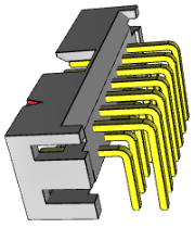 You can select this button - It will open these pin pattern options - 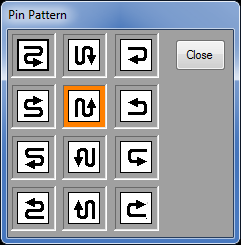 You don't need to rotate the part. And if you did need to rotate it use "Preferences". ------------- Stay connected - follow us! https://twitter.com/PCBLibraries" rel="nofollow - X - http://www.linkedin.com/company/pcb-libraries-inc-/" rel="nofollow - LinkedIn |
Posted By: DaveCowl
Date Posted: 19 May 2015 at 5:35pm
|
Indeed that is where I am at - I used the options to change the pin ordering. But I don't like having pin 1 in the top right corner since all the other parts are bottom left... |
Posted By: Tom H
Date Posted: 19 May 2015 at 5:44pm
|
I would not be concerned about connector rotations. They are going to be all over the map. Most connectors are created using the component mfr. pattern and if they put Pin 1 on the right so do we. Example 1: SAMTEC Post Headers for Single Row Pin 1 is on the Right but Dual Row pin 1 is on the Left. Example 2: Modular Jacks for RJ11 or RJ45 have pin 1 on both the left and right depending on the mfr. The best way to control the rotation so that it is saved in the FPX file is to convert the Calculator Connector to FP Designer then rotate any way you want and save to FPX. i.e.: the footprint rotation for Calculator parts use Preferences and this in not saved in FPX. But FP Designer rotations are saved to FPX. ------------- Stay connected - follow us! https://twitter.com/PCBLibraries" rel="nofollow - X - http://www.linkedin.com/company/pcb-libraries-inc-/" rel="nofollow - LinkedIn |
Posted By: Tom H
Date Posted: 03 Aug 2015 at 6:45pm
|
We just added Receptacle and Shrouded Vertical Headers with high quality 3D STEP in V2015.16 that will be available tomorrow. ------------- Stay connected - follow us! https://twitter.com/PCBLibraries" rel="nofollow - X - http://www.linkedin.com/company/pcb-libraries-inc-/" rel="nofollow - LinkedIn |