

|
|
Grid for Part Creation and Placement |
Post Reply 
|
| Author | |
USER2 
New User 
Joined: 09 Dec 2014 Status: Offline Points: 4 |
 Post Options Post Options
") Thanks(0) Thanks(0)
 Quote Reply Quote Reply
 Topic: Grid for Part Creation and Placement Topic: Grid for Part Creation and PlacementPosted: 30 Sep 2019 at 10:23am |
|
Hi, I have a basic question that i would like to hear opinions - What grid value we should use for any type of part creation? Surface Mount and Through-hole both small & big? What is the placement grid should be used for design? Thanks! |
|
 |
|

|
|
|
|
|
Tom H
Admin Group 

Joined: 05 Jan 2012 Location: San Diego, CA Status: Offline Points: 6088 |
Post Options
Thanks(0)
Quote Reply
Posted: 30 Sep 2019 at 10:42am |
|
It depends on the type of PCB layouts you have. High Density or Low Density.
For PCB layouts that have Low Density part placements, the best PCB library "Pad Size" round-off and "Pad Place Round-off" grid would be 0.05 mm. The Part Placement Grids are 1 mm for large parts, 0.5 mm for medium size parts and 0.1 mm for small parts. For PCB layouts that have High Density part placements, the best PCB library "Pad Size Round-off" and "Pad Place Round-off" grid would be 0.01 mm. The Part Placement Grids are 1 mm for large parts, 0.5 mm for medium size parts and 0.1 mm for small parts. Trace Width is 0.1 mm and route grid is 0.05 mm. Here is the routing example where SMD via fanout is on a 0.5 mm grid system placed 1 mm apart. 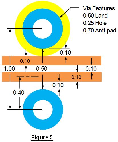 |
|
|
|
|
Post Reply
|
|
| Tweet |
| Forum Jump | Forum Permissions You cannot post new topics in this forum You cannot reply to topics in this forum You cannot delete your posts in this forum You cannot edit your posts in this forum You cannot create polls in this forum You cannot vote in polls in this forum |


 Topic Options