

 |

|
Staggered Pin BGAs |
Post Reply 
|
| Author | |
Nick B 
Admin Group 
Joined: 02 Jan 2012 Status: Offline Points: 1929 |
 Post Options Post Options
 Thanks(0) Thanks(0)
 Quote Quote  Reply Reply
 Topic: Staggered Pin BGAs Topic: Staggered Pin BGAsPosted: Yesterday at 7:37pm |
|
Creating Staggered Pin BGAs can be tricky. There are a couple ways:
You can easily create the footprint using a CSV text file with the pin names and X/Y coordinates (option 1). If you don't have a CSV file, try using the FP Designer "Pin Array Wizard" (option 2). This post will focus on the second option. BGA with Alphanumeric Rows: 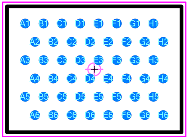 BGA with Alphanumeric Columns: 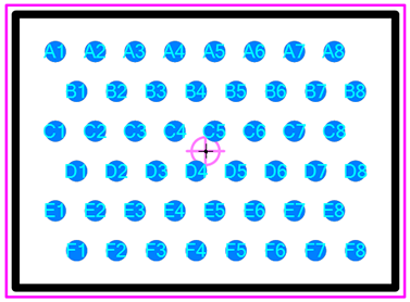 You need the package dimensions for Length, Width and Height. For this demo we'll use 7, 5, 2. You'll also need to know the Pin Pitch and Pad Diameter. For this demo we'll use 0.75 and 0.40. Select the "Designer" button and insert the package dimensions. 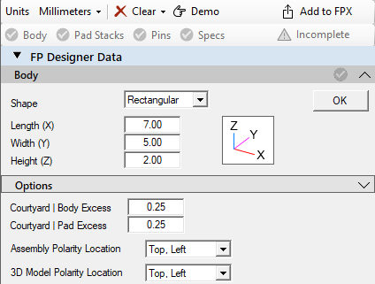 Select the OK button and the Drafting Outlines for Silkscreen, Assembly, Component, Courtyard and Origin will be auto generated. 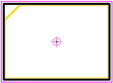 The Pad Stack Designer will automatically appear. Create a Round surface mount pad 0.40 diameter and select "Add Pad Stack to Design Queue" and then "Add Queue to Design". 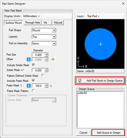 The Pad Stack Manager will automatically open to allow you to edit the pad stack layer sizes and shapes. If there are no edits, select "Save and Close". 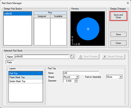 In the Define Placement menu select the "Open Wizard" button. When you enter simple values in the Wizard for Pin Count, Pin Pitch and Offset. Select "Apply Wizard" to populate the X/Y coordinates in the Pin Placement menu. Then enter the X Stagger dimension and enter "A" in the Alpha pin options. You will see an Example of the Alphanumeric Pin Assignments. Select the "Open Wizard" button. 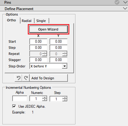
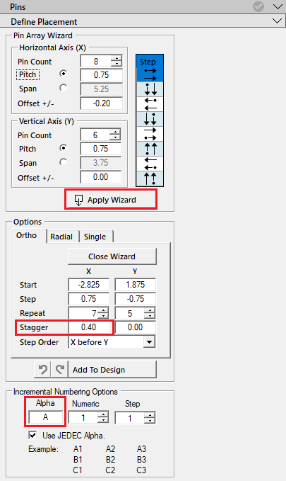 Select the "Add To Design" button 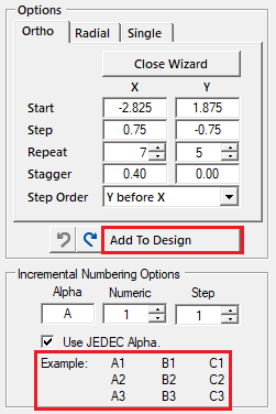 The pads will display in the Footprint Viewer with Alphanumeric Rows 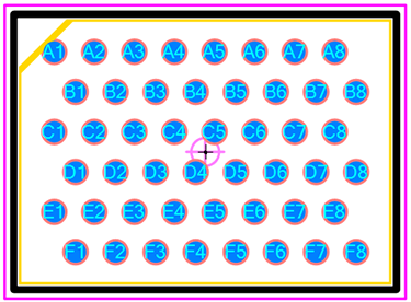 For Alphanumeric Columns select the Undo button Then select the Pin Array Wizard Pin Direction to Column (Blue highlight) 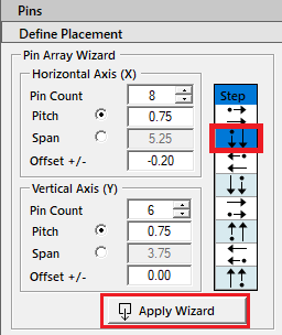 The new values will auto-populate the Pin Options cells. See the Example Pin Assignments. Select "Add To Design" button. 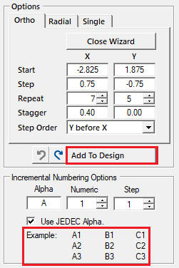 The pads will be added to the footprint in alphanumeric columns 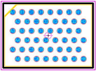 Add the footprint to your master FPX file and export to any CAD format. The BGA pin quantity limit is 99,999 pins. You can build any staggered pin BGA in minutes using the Pin Array Wizard  PCB Footprint Expert Simplify your PCB design process with the Footprint Expert, the ultimate tool for automating staggered pin BGAs. Automation helps ensures accurate, consistent, reliable footprints with minimal introduction of human error. Let the Footprint Expert handle your CAD library so you can focus on creating flawless PCB designs faster and more efficiently! Get your FREE Footprint Calculator or Footprint Expert Evaluation License: Call: 847-557-2300 |
|
 |
|
 |
|
Post Reply 
|
|
| Tweet |
| Forum Jump | Forum Permissions  You cannot post new topics in this forum You cannot reply to topics in this forum You cannot delete your posts in this forum You cannot edit your posts in this forum You cannot create polls in this forum You cannot vote in polls in this forum |