

|
|
Non-Symmetric Tolerance Question? |
Post Reply 
|
| Author | |
Eng. Jesus Mora 
Advanced User 

Joined: 11 Jul 2013 Status: Offline Points: 56 |
 Post Options Post Options
") Thanks(0) Thanks(0)
 Quote Reply Quote Reply
 Topic: Non-Symmetric Tolerance Question? Topic: Non-Symmetric Tolerance Question?Posted: 20 Jun 2018 at 4:38pm |
|
Hello,
I'm Calculating a tantalum cap with non symmetric tolerances , eg. "+20 , -10 " but when i save the part it converts it to " +/- 15" . how can i make the program not do that? 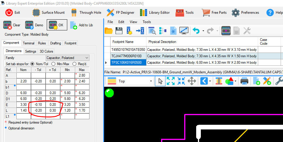 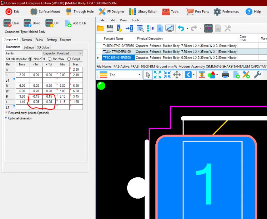 |
|
 |
|
|
|
|
Tom H
Admin Group 

Joined: 05 Jan 2012 Location: San Diego, CA Status: Offline Points: 5716 |
Post Options
Thanks(0)
Quote Reply
Posted: 20 Jun 2018 at 4:56pm |
|
The Nominal dimensions are used for the Footprint Name and the 3D STEP model. The Minimum and Maximum dimensions auto-calculate the Nominal dimension. Rather than entering a Nominal value with an offset tolerance, enter the Minimum and Maximum dimensions instead. Also, entering different + and - tolerances has no affect on the resulting footprint because the IPC mathematical model uses the Minimum and Maximum dimensions to calculate the pad size and location, not the Nominal dimension with offset tolerances. |
|
|
|
|
Eng. Jesus Mora
Advanced User
Joined: 11 Jul 2013 Status: Offline Points: 56 |
Post Options
Thanks(0)
Quote Reply
Posted: 21 Jun 2018 at 9:27am |
|
Hello Tom, thanks for the quick reply
So if I understand correctly what you are saying, if, for example, I have a datasheet that says my nominal is 3.2 with a +.20 / - .10, I should just enter a min of 3.1 and max of 3.4 right? That would give me a calculated nominal of 3.25 (using the calculated +/- .15 that the program creates on its own), so when importing the footprint, the Body Outline mechanical drawing will be done using that, instead of the 3.20 that the datasheet specifically says. This can throw off the person that verifies the footprint later on because when he goes to measure the body outline and compare it to what the datasheet says it will be different. Is there any way to maintain the dimensions and tolerances the same as what the datasheet says? Regards |
|
|
|
|
Tom H
Admin Group
Joined: 05 Jan 2012 Location: San Diego, CA Status: Offline Points: 5716 |
Post Options
Thanks(0)
Quote Reply
Posted: 21 Jun 2018 at 9:49am |
|
The mathematical model for footprint calculation comes from the Minimum and Maximum dimensions.
When you get a datasheet that has different + & - tolerances, do not enter the Nominal + tolerances, enter the Minimum & Maximum dimensions. Teach your checkers and QC to look at the Minimum & Maximum values, (not the tolerances). We will see if the new V2019 code can be written to allow for different + & - tolerances. But the current Library Expert V2018 cannot be updated to accommodate this feature. |
|
|
|
|
Post Reply
|
|
| Tweet |
| Forum Jump | Forum Permissions You cannot post new topics in this forum You cannot reply to topics in this forum You cannot delete your posts in this forum You cannot edit your posts in this forum You cannot create polls in this forum You cannot vote in polls in this forum |


 Topic Options