

|
|
Non-Polar Part Still Displays Dot in 3D Step |
Post Reply 
|
| Author | |
ChrisChris 
Advanced User 
Joined: 03 Nov 2021 Status: Offline Points: 92 |
 Post Options Post Options
") Thanks(0) Thanks(0)
 Quote Reply Quote Reply
 Topic: Non-Polar Part Still Displays Dot in 3D Step Topic: Non-Polar Part Still Displays Dot in 3D StepPosted: 20 Feb 2022 at 4:51pm |
|
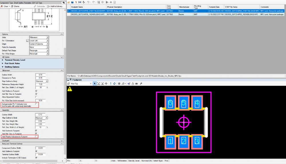
If I build a part using the Calculator with the following settings applied, the silkscreen and assembly drawing are rendered as expected but the 3D-model still includes the pin 1 dot. Do I need to make the 3D model separately using FP Designer in order to remove the dot or is there another option I'm missing somewhere for accomplishing this using the calculator?
 Thanks, Chris
|
|
 |
|
|
|
|
Tom H
Admin Group 

Joined: 05 Jan 2012 Location: San Diego, CA Status: Offline Points: 5716 |
Post Options
Thanks(0)
Quote Reply
Posted: 20 Feb 2022 at 5:07pm |
|
Probably.
The dot on the 3D STEP to denote pin 1 like the physical package may indicate Pin 1. But you can change the Polarity Dot Color in the 3D model by making it the same color as the package body. All 3D color changes are saved to FPX. |
|
|
|
|
ChrisChris
Advanced User
Joined: 03 Nov 2021 Status: Offline Points: 92 |
Post Options
Thanks(0)
Quote Reply
Posted: 20 Feb 2022 at 5:15pm |
|
OK, I think the easiest thing to do would be to change the dot color to black. The physical packages in these cases do not indicate pin-1 polarity. At least that's what their datasheets say. Kind of annoying. Diodes Inc has a bunch of these SOT-23-6 parts such that when the diode array is laid out in such a way that the part orientation is a don't care they leave the pin-1 mark off the package. Seems like more trouble/confusion than it's worth. Wish everyone would just keep it simple and specify a polarity marker whether it's needed or not.
|
|
|
|
|
Tom H
Admin Group
Joined: 05 Jan 2012 Location: San Diego, CA Status: Offline Points: 5716 |
Post Options
Thanks(0)
Quote Reply
Posted: 20 Feb 2022 at 5:26pm |
|
Diodes, Inc. is the only component manufacturer that I know that uses the same Case Code for multiple packages.
In this scenario, the SOT-353 is the standard package and SOT353 for the non-standard package. We can't invent Case Codes because there are thousands of POD users that search by Case Code. In the future, we were planning to have the new PCBPOD website pulling the existing mfr. Case Code into a new part number search to increase the hit ratio. I don't know if we can do that with Diodes, Inc. |
|
|
|
|
Post Reply
|
|
| Tweet |
| Forum Jump | Forum Permissions You cannot post new topics in this forum You cannot reply to topics in this forum You cannot delete your posts in this forum You cannot edit your posts in this forum You cannot create polls in this forum You cannot vote in polls in this forum |


 Topic Options