

|
|
3D Color Options in FP Designer |
Post Reply 
|
| Author | |
ChrisChris 
Advanced User 
Joined: 03 Nov 2021 Status: Offline Points: 92 |
 Post Options Post Options
") Thanks(0) Thanks(0)
 Quote Reply Quote Reply
 Topic: 3D Color Options in FP Designer Topic: 3D Color Options in FP DesignerPosted: 16 Feb 2022 at 9:33am |
|
Hello,
Is there a way to more fully specify the 3D color features in the models created using FP Designer similar to what's provided for the SMT calculator? I would like to define lead colors different than the body for caps, for example, as in the calculator options: 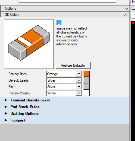 I guess I've been under the impression that FP Designer would allow me to fully customize anything and everything that the calculators do automatically. Thanks, Chris
|
|
 |
|
|
|
|
ChrisChris
Advanced User
Joined: 03 Nov 2021 Status: Offline Points: 92 |
Post Options
Thanks(0)
Quote Reply
Posted: 16 Feb 2022 at 9:52am |
|
Note I understand that the tool would need leads data in order to color the leads differently. I guess I'm asking why FP Designer does not allow me to input this data so that I can have nice full-featured footprints that include terminal outlines and 3D-Bodies that include the terminal colorings the way the calculators do?
I unfortunately just spent all day yesterday creating 120 custom footprints in FP Designer because I need a bunch of different Courtyard Excess and body thickness combinations across the entire family of parts (so I can't use the calculators) and now I have 120 3D models that look like BGAs instead of caps with terminals. If I can't do this in FP Designer then it seems like my only option is to create the 3D models separately using the calculators and then merging the exports to get them into Altium.
|
|
|
|
|
Tom H
Admin Group 

Joined: 05 Jan 2012 Location: San Diego, CA Status: Offline Points: 5716 |
Post Options
Thanks(0)
Quote Reply
Posted: 16 Feb 2022 at 9:52am |
|
All the features in a 3D model are derived from the package dimensions in the Calculator.
The only dimensions in FP Designer are the Body L x W X H. No terminal lead dimensions because FP Designer is a catch all for non-standard packages with many lead forms. The recommended 3D STEP model for FP Designer parts is from the component manufacturer or the Footprint Expert Calculator. The FP Designer 3D model is an Extruded Block, but you can add a Polarity Marker in any corner and change the model color. |
|
|
|
|
ChrisChris
Advanced User
Joined: 03 Nov 2021 Status: Offline Points: 92 |
Post Options
Thanks(0)
Quote Reply
Posted: 16 Feb 2022 at 9:53am |
|
Note I understand that the tool would need leads data in order to color the leads differently. I guess I'm asking why FP Designer does not allow me to input this data so that I can have nice full-featured footprints that include terminal outlines and 3D-Bodies that include the terminal colorings the way the calculators do?
I unfortunately just spent all day yesterday creating 120 custom footprints in FP Designer because I need a bunch of different Courtyard Excess and body thickness combinations across the entire family of parts (so I can't use the calculators) and now I have 120 3D models that look like BGAs instead of caps with terminals. If I can't do this in FP Designer then it seems like my only option is to create the 3D models separately using the calculators and then merging the exports to get them into Altium.
|
|
|
|
|
ChrisChris
Advanced User
Joined: 03 Nov 2021 Status: Offline Points: 92 |
Post Options
Thanks(0)
Quote Reply
Posted: 16 Feb 2022 at 9:55am |
|
But FP Designer knows I'm making a cap because I have to enter the description category. So, open-ended or not, it seems like that is a guiding precedent.
|
|
|
|
|
Tom H
Admin Group
Joined: 05 Jan 2012 Location: San Diego, CA Status: Offline Points: 5716 |
Post Options
Thanks(0)
Quote Reply
Posted: 16 Feb 2022 at 9:55am |
|
Create a separate FPX file with the package dimensions and output perfect 3D STEP models.
Call the FPX file "CHIP_3D.fpx" or whatever. |
|
|
|
|
ChrisChris
Advanced User
Joined: 03 Nov 2021 Status: Offline Points: 92 |
Post Options
Thanks(0)
Quote Reply
Posted: 16 Feb 2022 at 10:03am |
|
OK, this is really unfortunate and requires me to essentially enter all of the data again, this time using the calculators. It seems like there's a missed opportunity here to leverage the calculator functionality within FP Designer to do the initial heavy lifting and then once customizations are applied the front-end calculator stuff gets locked in and can't be changed. For example, use Specifications->Description Category to define the base 3D-color options. I don't know. Just feels disappointing in that I was expecting FP Designer to be the Cadillac that would allow me to fully customize both the footprint and 3D-body if I wanted to go beyond the basic calculators.
|
|
|
|
|
Tom H
Admin Group
Joined: 05 Jan 2012 Location: San Diego, CA Status: Offline Points: 5716 |
Post Options
Thanks(0)
Quote Reply
Posted: 16 Feb 2022 at 10:17am |
|
The perfect way to do what you did would be to create any standard footprint in the Calculator first and get it as close as you can with all the features you need and save to FPX and then move to FP Designer to further edit the footprint to fully customize it.
Then you have the Calculator and FP Designer version in FPX and no double work. |
|
|
|
|
ChrisChris
Advanced User
Joined: 03 Nov 2021 Status: Offline Points: 92 |
Post Options
Thanks(0)
Quote Reply
Posted: 16 Feb 2022 at 10:24am |
|
So you are saying that I can open a part that was originally created using the SMT calculator, click on the FP Designer tab, change the Courtyard Excess, and save the part, and now the custom courtyard excess is stored in the FPX along with a 3D-model that includes the terminals? I was under the (false) impression that the calculator and FP Designer are a one or the other thing.
|
|
|
|
|
Post Reply
|
|
| Tweet |
| Forum Jump | Forum Permissions You cannot post new topics in this forum You cannot reply to topics in this forum You cannot delete your posts in this forum You cannot edit your posts in this forum You cannot create polls in this forum You cannot vote in polls in this forum |


 Topic Options