

|
|
Molded body polarity marking |
Post Reply 
|
| Author | |
Tempest 
Active User 
Joined: 20 Jun 2012 Location: Oregon Status: Offline Points: 20 |
 Post Options Post Options
") Thanks(0) Thanks(0)
 Quote Reply Quote Reply
 Topic: Molded body polarity marking Topic: Molded body polarity markingPosted: 25 Jun 2019 at 8:16am |
|
On a 3D step model, wondering why I'm not seeing a polarity mark on a molded body inductor, is the 3d step just not supporting this?It's been like this for a while just curious.
Thanks,
Paul |
|
 |
|

|
|
|
|
|
Tom H
Admin Group 

Joined: 05 Jan 2012 Location: San Diego, CA Status: Offline Points: 6088 |
Post Options
Thanks(0)
Quote Reply
Posted: 25 Jun 2019 at 9:30am |
|
The Molded Body Inductor is bi-directional.
It can be inverted during assembly. Can you provide the URL link to a datasheet that has a Polarized Inductor? |
|
|
|
|
Tempest
Active User
Joined: 20 Jun 2012 Location: Oregon Status: Offline Points: 20 |
Post Options
Thanks(0)
Quote Reply
Posted: 25 Jun 2019 at 9:46am |
|
Hi Tom,
Some indicate polarity like the Panasonic part number
ETQP4M220YFP, regardless as to if that is true or not. The software does give the option for polarized inductor so I'd kinda expect a pin 1 indicator. Thanks, Paul |
|
|
|
|
Tom H
Admin Group
Joined: 05 Jan 2012 Location: San Diego, CA Status: Offline Points: 6088 |
Post Options
Thanks(0)
Quote Reply
Posted: 25 Jun 2019 at 10:01am |
|
Here is the Panasonic ETQP4M220YFP Molded Body Inductor.
Download it here (much more Terminal Lead Detail) - 3D STEP Here is what it looks like and I don't see any Polarity Marking - 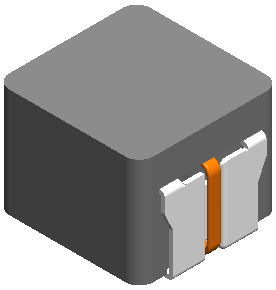 |
|
|
|
|
Tempest
Active User
Joined: 20 Jun 2012 Location: Oregon Status: Offline Points: 20 |
Post Options
Thanks(0)
Quote Reply
Posted: 25 Jun 2019 at 10:10am |
|
Thank you Tom for looking this up, nice model.
I'm still wondering though, is Lib expert not supporting inductor polar marking and if not is it going to be. If not maybe consider removing the option. Thank you
|
|
|
|
|
Tom H
Admin Group
Joined: 05 Jan 2012 Location: San Diego, CA Status: Offline Points: 6088 |
Post Options
Thanks(0)
Quote Reply
Posted: 25 Jun 2019 at 10:16am |
|
We only add Polarity Markings to packages that are polarized.
Show me a polarized inductor and we'll add it. Otherwise, all inductors like all resistors, can be inverted during assembly. We do not want to confuse the assembly process with unnecessary polarity markings. |
|
|
|
|
Ian S
Committee 
Joined: 21 Aug 2014 Status: Offline Points: 67 |
Post Options
Thanks(0)
Quote Reply
Posted: 26 Jun 2019 at 1:24am |
|
Following up on this subject here's some inductor polarity-related reading:
Ian |
|
|
|
|
Tom H
Admin Group
Joined: 05 Jan 2012 Location: San Diego, CA Status: Offline Points: 6088 |
Post Options
Thanks(1)
Quote Reply
Posted: 26 Jun 2019 at 6:48am |
|
Ian - These are good articles. I wonder why the manufacturer's 3D models do't have a polarity marking.
I've been involved in over 2,000 PCB layouts since 1974 and I've never added Polarity Marking on Inductors on the silkscreen Legend. I'm going to rethink this for the future. Thanks! |
|
|
|
|
5not4
Active User
Joined: 09 Jul 2013 Status: Offline Points: 40 |
Post Options
Thanks(0)
Quote Reply
Posted: 01 Jul 2019 at 6:53am |
|
We've been including a Pin 1 indicator on inductors when the manufacturer supplies it for the past few years.
It was discovered during EMC testing that the polarity (a term I find inaccurate, should be more related to Pin 1 or the winding start pin) could be critical during PCB layout.
|
|
|
|
|
Tom H
Admin Group
Joined: 05 Jan 2012 Location: San Diego, CA Status: Offline Points: 6088 |
Post Options
Thanks(0)
Quote Reply
Posted: 01 Jul 2019 at 7:35am |
|
You should add a Pin 1 polarity marking on the silkscreen legend and the assembly drawing.
This would help the assembly process, but also increase the performance of the PCB layout. I haven't seen a Pin 1 polarity marking on the mfr. provided 3D STEP models. If you have inductors lined up side by side, it's a good idea to point all Pin 1's in the same direction so that all the coil starting points are in the same direction. |
|
|
|
|
Post Reply
|
|
| Tweet |
| Forum Jump | Forum Permissions You cannot post new topics in this forum You cannot reply to topics in this forum You cannot delete your posts in this forum You cannot edit your posts in this forum You cannot create polls in this forum You cannot vote in polls in this forum |


 Topic Options