

|
|
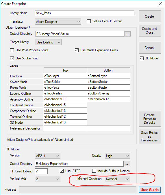
"Material Condition" for 3D model |
Post Reply 
|
| Author | |
ransonjd 
Committee 
Joined: 15 Nov 2016 Status: Offline Points: 144 |
 Post Options Post Options
") Thanks(1) Thanks(1)
 Quote Reply Quote Reply
 Topic: "Material Condition" for 3D model Topic: "Material Condition" for 3D modelPosted: 05 Jan 2017 at 2:49pm |
|
What does the "Material Condition" drop down change when building 3D models for a component?
--JOhn
|
|
 |
|

|
|
|
|
|
Tom H
Admin Group 

Joined: 05 Jan 2012 Location: San Diego, CA Status: Offline Points: 6088 |
Post Options
Thanks(0)
Quote Reply
Posted: 05 Jan 2017 at 3:01pm |
|
In the Calculator dimensional panel the user either inputs the Nominal & Tolerance or the Minimum and Maximum package values. If you insert Nominal and Tolerance. the dimensional panel auto-fills the Min & Max dimensions. If you insert the Min & Max dimensions the dimensional panel auto-fills the Nominal and Tolerance values. Either way, Minimum, Nominal and Maximum dimensions are always there. When creating the 3D STEP model the Material Condition setting will use the dimensional data in whatever column it's set to. i.e.: if you select Maximum Material Condition then the 3D STEP model uses the Maximum package dimensions to create the model. Note: you can insert 100 million different component package dimensions and auto-generate 100 million 3D STEP models. I say this because some users do not realize that every 3D model is 100% customized per the package dimensions in the Land Pattern Calculator. |
|
|
|
|
ransonjd
Committee
Joined: 15 Nov 2016 Status: Offline Points: 144 |
Post Options
Thanks(1)
Quote Reply
Posted: 05 Jan 2017 at 5:12pm |
|
Okay, that's what I suspected. It seemed like it wasn't working, but I just realized that the part was created in FP Designer and the body is not toleranced.
--John
|
|
|
|
|
Tom H
Admin Group
Joined: 05 Jan 2012 Location: San Diego, CA Status: Offline Points: 6088 |
Post Options
Thanks(0)
Quote Reply
Posted: 05 Jan 2017 at 5:56pm |
|
I should have put emphases on "Calculator" parts with all package dimensions and not Non-standard mfr. recommended patterns (FP Designer). |
|
|
|
|
Post Reply
|
|
| Tweet |
| Forum Jump | Forum Permissions You cannot post new topics in this forum You cannot reply to topics in this forum You cannot delete your posts in this forum You cannot edit your posts in this forum You cannot create polls in this forum You cannot vote in polls in this forum |


 Topic Options