|
|
Through-hole Solder & Paste Mask Pad Stack Issue |
Post Reply 
|
| Author | |
m.elsayed 
Expert User 
Joined: 22 Sep 2016 Status: Offline Points: 203 |
 Post Options Post Options
") Thanks(0) Thanks(0)
 Quote Reply Quote Reply
 Topic: Through-hole Solder & Paste Mask Pad Stack Issue Topic: Through-hole Solder & Paste Mask Pad Stack IssuePosted: 20 Oct 2025 at 12:13pm |
|
While I use Footprint Expert for creating a through-hole footprint, I find paste mask and solder mask not equal to Zero '0', also pad type not be simple type.
|
|
 |
|

|
|
|
|
|
Tom H
Admin Group 

Joined: 05 Jan 2012 Location: San Diego, CA Status: Offline Points: 5939 |
Post Options
Thanks(0)
Quote Reply
Posted: Yesterday at 10:29am |
|
What's wrong with having negative values?
When a negative paste mask value is the same value as the pad, it turns off that shape. We don't understand what the issue is. We know that you want to see a zero '0' for the paste mask if there is none, but having a negative value is the same thing. |
|
|
|
|
m.elsayed
Expert User
Joined: 22 Sep 2016 Status: Offline Points: 203 |
Post Options
Thanks(0)
Quote Reply
Posted: Yesterday at 12:35pm |
|
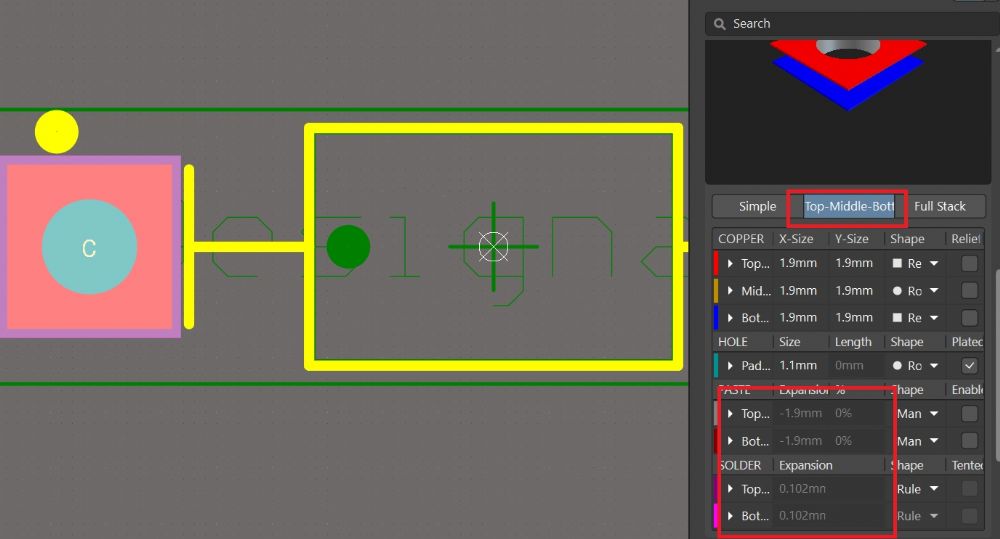
1st - Pad type should be simple, not like shown in image
2nd - Solder Mask expansion = 0 and select not inherit Altium rule when building 3rd - Paste Mask value for fiducials should equal 0. However, a negative value appears |
|
|
|
|
Tom H
Admin Group
Joined: 05 Jan 2012 Location: San Diego, CA Status: Offline Points: 5939 |
Post Options
Thanks(0)
Quote Reply
Posted: Yesterday at 12:57pm |
|
There is no such thing as a negative Solder Mask on a pad.
i.e.: all SMD and PTH pads must have Solder Mask. The only time the value is negative is when the pad stack uses Solder Mask Defined technology. The Negative Paste Mask value only appears in Fiducials. Note: no one uses Local Fiducials any more. Ask your assembly shop if they need them. Surface Mount pad stack Paste Mask is the same value as the pad (1:1 scale) except for Thermal Pad checker board patterns. Through-hole pad stacks do not use Paste Mask unless you are using Pin-in-Paste (PnP) technology. If you use PnP technology then the Paste Mask value is normally 1:1 scale of the pad size (or bigger). |
|
|
|
|
Jeff.M
Admin Group

Joined: 16 May 2012 Location: San Diego Status: Offline Points: 491 |
Post Options
Thanks(0)
Quote Reply
Posted: 18 hours 9 minutes ago at 6:39pm |
|
The negative values are an artifact of the Altium translator script.
They are part of a perfectly good Altium footprint. Once the footprint is: imported into an Altium library; the library is saved; Altium is closed, then reopened the values will be appear as zero. There have never been any reported problems associated with this characteristic.
|
|
|
|
|
Tom H
Admin Group
Joined: 05 Jan 2012 Location: San Diego, CA Status: Offline Points: 5939 |
Post Options
Thanks(0)
Quote Reply
Posted: 16 hours 26 minutes ago at 8:22pm |
|
When you first import a part from footprint expert into Altium, but through hole pad stack will show a negative pace mask value.
However, when you close to him and reopen it and select the properties for the pad stack, the pace mask value will be zero. The negative value is only there temporarily until you close Altium and reopen it and everything is reset to normal.
|
|
|
|
|
m.elsayed
Expert User
Joined: 22 Sep 2016 Status: Offline Points: 203 |
Post Options
Thanks(0)
Quote Reply
Posted: 14 hours 40 minutes ago at 10:08pm |
|
Thanks , Tom, Jeff, got your reply for this point and will follow it and check
but still wait your support for the other 2 points:- 1- pad type should be simple not other type as shown in image 2- solder mask expansion should be zero not have vlaue
|
|
|
|
|
m.elsayed
Expert User
Joined: 22 Sep 2016 Status: Offline Points: 203 |
Post Options
Thanks(0)
Quote Reply
Posted: 12 hours 27 minutes ago at 12:21am |
|
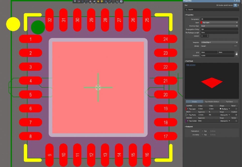
i try the point for paste mask expansion , but till gives negative vlaues as shown in screen
 |
|
|
|
|
Tom H
Admin Group
Joined: 05 Jan 2012 Location: San Diego, CA Status: Offline Points: 5939 |
Post Options
Thanks(0)
Quote Reply
Posted: 4 hours 42 minutes ago at 8:06am |
|
The thermal pad has a checker board paste mask pattern.
Can you manually create a thermal pad with a checker board paste mask pattern and send us the Altium .pcblib file via email so we can compare the results? We don't use Altium as a PCB design tool, so it would be best coming from you. |
|
|
|
|
Post Reply
|
|
| Tweet |
| Forum Jump | Forum Permissions You cannot post new topics in this forum You cannot reply to topics in this forum You cannot delete your posts in this forum You cannot edit your posts in this forum You cannot create polls in this forum You cannot vote in polls in this forum |


 Topic Options