

|
|
Rounded Rectangular Pad Shape |
Post Reply 
|
| Author | |
bnoel 
Active User 

Joined: 14 Mar 2014 Location: Western NY Status: Offline Points: 14 |
 Post Options Post Options
") Thanks(0) Thanks(0)
 Quote Reply Quote Reply
 Topic: Rounded Rectangular Pad Shape Topic: Rounded Rectangular Pad ShapePosted: 08 Jun 2017 at 6:13am |
|
Hello - We have a library including almost 6000 parts. Around 90% of our footprints have been created using rectangular pads. We are considering migrating to rounded rectangular pads based on some of the recommendations I've seen on this forum.
We use OrCAD Padstack Editor version 17.2-2016 for our padstack creation. The Padstack Editor includes the option to convert rectangular pads to rounded rectangular pads. By default the editor calculates the radius of the rounded corners to be one third of the smaller of the 2 rectangle dimensions. For instance a rectangular pad of 1.20 mm X 0.80 mm when converted to a rounded rectangular pad would use 0.267 mm for the radius (0.80 / 3) Is this an acceptable approach? |
|
 |
|

|
|
|
|
|
Tom H
Admin Group 

Joined: 05 Jan 2012 Location: San Diego, CA Status: Offline Points: 6074 |
Post Options
Thanks(0)
Quote Reply
Posted: 08 Jun 2017 at 7:53am |
|
In Library Expert Pro there are Rule Settings for -
- Corner Radius % of pad width - the default is 25% - Corner Radius Limit - the default is 0.25 mm - Corner Radius Round-off - the default is 0.01 But these values are all user definable. Rounded Rectangle pad shape conforms to the paste mask stencil aperture opening. The stencil maker uses a laser to cut the aperture openings and rounds the corners of rectangular shapes to increase the stencil release yield. Typical Stencil - 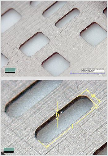
|
|
|
|
|
bnoel
Active User
Joined: 14 Mar 2014 Location: Western NY Status: Offline Points: 14 |
Post Options
Thanks(0)
Quote Reply
Posted: 08 Jun 2017 at 11:56am |
|
Two additional questions about rounded rectangular pads:
1. If a mfr recommends rectangular pads should we change them to rounded rectangular pads? 2. What about large components? For example, we have a 10.3mm X 10.3mm X 10.3mm Aluminum Electrolytic Cap with 4.3mm X 2.1mm pads. Should we change these to rounded rectangles?
|
|
|
|
|
Tom H
Admin Group
Joined: 05 Jan 2012 Location: San Diego, CA Status: Offline Points: 6074 |
Post Options
Thanks(0)
Quote Reply
Posted: 08 Jun 2017 at 12:27pm |
|
Texas Instruments is starting to promote 0.05 mm radius corners on their new parts. Other mfr.'s are starting to recommend rounded rectangle pad shape too, but even if they don't we still do.
All rectangular pad get a corner radius except DFN & LGA where the lead is BTC (Bottom Termination Component) and the pad size is equal to the Terminal Lead size or a 0.05 mm periphery. |
|
|
|
|
robmeyer
Advanced User 
Joined: 04 Oct 2012 Status: Offline Points: 113 |
Post Options
Thanks(0)
Quote Reply
Posted: 02 Feb 2018 at 5:22am |
|
Hello,
in Version 2017.22 and 2018.1 Library expert using other rules for the exception: Here it is per default rounded padshape under LGA. Also the Tab under QFN is now per default rounded. I have in mind, that in older Versions per default this was a square. Why this change? Thanks Robert
|
|
|
|
|
Tom H
Admin Group
Joined: 05 Jan 2012 Location: San Diego, CA Status: Offline Points: 6074 |
Post Options
Thanks(0)
Quote Reply
Posted: 02 Feb 2018 at 8:21am |
|
In order for any Thermal Tab to have Rounded Corners, the user must enter a value for "tr" in the Calculator. I have never used Rounded Corners for Thermal Pads. Can you please send us a FPX file so we can prove it.
The LGA has always had radius corners on square Leaded parts but that can easily be changed in Preferences. |
|
|
|
|
robmeyer
Advanced User
Joined: 04 Oct 2012 Status: Offline Points: 113 |
Post Options
Thanks(0)
Quote Reply
Posted: 05 Feb 2018 at 7:45am |
|
Hi,
you are right, the tr value I have overseen in the Demopart. And that the default rounded square for LGA could be changed to square I know. But in the earlier post it sounds that it should be per default square and not Rounded square. For DFN it was done but not for LGA. So what is correct? Thanks Robert
|
|
|
|
|
Tom H
Admin Group
Joined: 05 Jan 2012 Location: San Diego, CA Status: Offline Points: 6074 |
Post Options
Thanks(0)
Quote Reply
Posted: 05 Feb 2018 at 8:18am |
|
We can change the default LGA pad shape from Rounded Rectangle to Square.
I think that's a good recommendation. Thanks!
|
|
|
|
|
Post Reply
|
|
| Tweet |
| Forum Jump | Forum Permissions You cannot post new topics in this forum You cannot reply to topics in this forum You cannot delete your posts in this forum You cannot edit your posts in this forum You cannot create polls in this forum You cannot vote in polls in this forum |


 Topic Options