
 |

|
Rounded Rectangle Radius is Different in Altium |
Post Reply 
|
Page 12> |
| Author | |
MSM_KOPF 
Advanced User 
Joined: 02 Feb 2015 Status: Offline Points: 53 |
 Post Options Post Options
 Thanks(0) Thanks(0)
 Quote Quote  Reply Reply
 Topic: Rounded Rectangle Radius is Different in Altium Topic: Rounded Rectangle Radius is Different in AltiumPosted: 26 Feb 2015 at 1:47am |
|
V2015-08
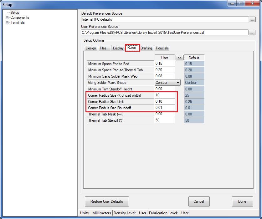
we are using SMD Pads rounded rectangle with corner radius set to maximum 10% Using IPC-7351-B Default Preferences (the new one for V2015-09 with contour courtyard disabled) User Setup Rules Corner Radius Size 10% (Default 25) and limit set to 0.10 (Default 0.25) For SMD Component QFN with tab our settings are ignored and instead it looks like calculated values are used 22% instead of our maximum value of 10% SOT223 will follow the maximum 10% only for the pad 4, as pad 1 to 3 use higher calculated values. |
|
 |
|

|
|
 |
|
Jeff.M 
Admin Group 

Joined: 16 May 2012 Location: San Diego Status: Offline Points: 485 |
 Post Options Post Options
 Thanks(0) Thanks(0)
 Quote Quote  Reply Reply
 Posted: 26 Feb 2015 at 7:52am Posted: 26 Feb 2015 at 7:52am |
|
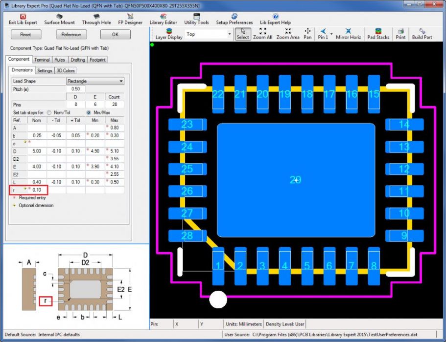
Thermal Tab corner radius (for QFP's QFN's, SO's & SON's isn't a percent but is set directly using the "r" value in component dimensions.
Corner chamfer is similarly set but with the "c" value. The SOT223 just has a large pin which is not considered a thermal tab. DPAK Thermal Tabs have no corner radius options.
|
|
 |
|
MSM_KOPF 
Advanced User 
Joined: 02 Feb 2015 Status: Offline Points: 53 |
 Post Options Post Options
 Thanks(0) Thanks(0)
 Quote Quote  Reply Reply
 Posted: 26 Feb 2015 at 9:18am Posted: 26 Feb 2015 at 9:18am |
|
I don't mean the thermal tab inside the QFN.
instead the pads around the thermal pad regarding QFN with tab Regarding SOT223, this footprint has 4 pads again no thermal tab, and these 4 pads are rounded rectangles were only the big pad 4 follows the setup for limitation of the corner radius size 10% So why does pad 4 follow the setup limit and the 3 other pads not ? I assume this is a bug. |
|
 |
|
Tom H 
Admin Group 

Joined: 05 Jan 2012 Location: San Diego, CA Status: Offline Points: 5917 |
 Post Options Post Options
 Thanks(0) Thanks(0)
 Quote Quote  Reply Reply
 Posted: 26 Feb 2015 at 10:10am Posted: 26 Feb 2015 at 10:10am |
|
I'm using the current V2015.09 pre-release and I am not seeing the problem that you are referring to.
I changed my user preferences to 10% for Rounded Rectangle pad shape and it's working like normal for every component family. Can you be more specific with numbers? Tell us your pad width and the pad stack name.
|
|
 |
|
MSM_KOPF 
Advanced User 
Joined: 02 Feb 2015 Status: Offline Points: 53 |
 Post Options Post Options
 Thanks(0) Thanks(0)
 Quote Quote  Reply Reply
 Posted: 27 Feb 2015 at 12:09am Posted: 27 Feb 2015 at 12:09am |
|
V2015-08 setup as mention
choose Surface mount -> SOT223 -> Reference this will create SOT223-SOT230P700X180-4L40N Export to Altium via Script Import and check the 4 pads Pad 1-3 1.97mm x 0.89mm rounded rectangle 20% Pad 4 1.97mm x 3.19mm rounded rectangle 10% surface mount -> qfn with tab - reference creates QFN50P500X400X80-29T255X355N Pad 1-28 0.86mm x 0.27mm rounded rectangle 22% Thermal Pad 2.55mm x 4.01mm with an edge ~0.35mm and 3x radius 0.05 |
|
 |
|
Tom H 
Admin Group 

Joined: 05 Jan 2012 Location: San Diego, CA Status: Offline Points: 5917 |
 Post Options Post Options
 Thanks(0) Thanks(0)
 Quote Quote  Reply Reply
 Posted: 27 Feb 2015 at 5:57am Posted: 27 Feb 2015 at 5:57am |
|
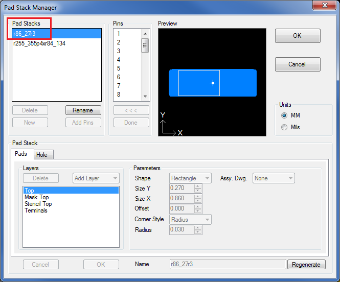
Let's handle this one part at a time. First the QFN. Here are the User Preference > Rules > Corner Radius -  Here is the QFN50P500X400X80-29T255X355 pad stacks. As you can see, the Pad Width = 0.27 mm and 10% = 0.027 with a round-off of 0.01 = 0.03 Thus the pad stack name = r86_27r3  Why do you continue to mention the Thermal Pad? It's corner radius is determined in the component dimensions.  |
|
 |
|
Tom H 
Admin Group 

Joined: 05 Jan 2012 Location: San Diego, CA Status: Offline Points: 5917 |
 Post Options Post Options
 Thanks(0) Thanks(0)
 Quote Quote  Reply Reply
 Posted: 27 Feb 2015 at 6:11am Posted: 27 Feb 2015 at 6:11am |
|
OK, I can see what's happening here. The Library Expert calculates corner radius by the pad width X 10% for each corner.
I import the QFN into Altium Designer and query the pad stack and the Rounded Corner radius indicates 22% over all. It seems that Altium percentage is 10% overall which means that it's 5% in each corner. If you change the Library Expert to be 5% corner radius with a 0.001 mm round-off you will get the correct result you're looking for in Altium. |
|
 |
|
robmeyer 
Advanced User 
Joined: 04 Oct 2012 Status: Offline Points: 113 |
 Post Options Post Options
 Thanks(0) Thanks(0)
 Quote Quote  Reply Reply
 Posted: 27 Feb 2015 at 6:33am Posted: 27 Feb 2015 at 6:33am |
|
The Corner Radius in Altium is 50% from the smallest side.
So when Pad Width is 0.27 mm and you have a radius if 22% you should get a radius of 0.0297mm.
So for Altium 10% should be 20%. |
|
 |
|
Tom H 
Admin Group 

Joined: 05 Jan 2012 Location: San Diego, CA Status: Offline Points: 5917 |
 Post Options Post Options
 Thanks(0) Thanks(0)
 Quote Quote  Reply Reply
 Posted: 27 Feb 2015 at 6:40am Posted: 27 Feb 2015 at 6:40am |
|
50% in each pad corner = a Full radius.
However, 50% total overall = 25% in each corner. Altium is doubling Library Expert numbers. There is a big difference of 25% in each corner or 25% overall = 12.5% in each corner. Do like I said and make Library Expert 5% corner radius with a 0.001 round-off and you'll get what you are looking for in Altium. |
|
 |
|
MSM_KOPF 
Advanced User 
Joined: 02 Feb 2015 Status: Offline Points: 53 |
 Post Options Post Options
 Thanks(0) Thanks(0)
 Quote Quote  Reply Reply
 Posted: 27 Feb 2015 at 6:47am Posted: 27 Feb 2015 at 6:47am |
|
Hi Tom,
what i am asking for is, how to setup this tool that at the end after import into altium all rounded rectangle pads report "corner Radius (%) = 10%" regardless of their pad size. and this for all footprints. by changing user setup rules to Corner Radius Size 5 Corner Radius Size Roundoff 0.001 for the SOT223 default reference pad 1-3 now have 10% but pad 4 is now set to 5% |
|
 |
|
Post Reply 
|
Page 12> |
| Tweet |
| Forum Jump | Forum Permissions  You cannot post new topics in this forum You cannot reply to topics in this forum You cannot delete your posts in this forum You cannot edit your posts in this forum You cannot create polls in this forum You cannot vote in polls in this forum |