Molded Body D – D1 nominal not to exceed 0.60 mm
Printed From: PCB Libraries Forum
Category: PCB Footprint Expert
Forum Name: Questions & Answers
Forum Description: issues and technical support
URL: https://www.PCBLibraries.com/forum/forum_posts.asp?TID=3337
Printed Date: 26 Jun 2026 at 9:55am
Topic: Molded Body D – D1 nominal not to exceed 0.60 mm
Posted By: GrungyRemnant
Subject: Molded Body D – D1 nominal not to exceed 0.60 mm
Date Posted: 01 Dec 2023 at 10:43am
|
Hi. I have a question regarding the Molded Body family. In version 13 this feature was added: Added D – D1 nominal not to exceed 0.60 mm error flag We’ve come across a few parts that do not meet this requirement. An example is TDK T491C337K004AT. For this TDK part dim D1 is not provided in the datasheet so I used the
D length – (lead thickness x 2) = 5.74 with the same 0.3 tolerance. This value is confirmed by measurements on the step model
provided by TDK. I've attached an image below showing the values.
The wizard will not accept this value as it does not meet the above condition. How should we create this part? Would we need to add an incorrect value that meets the rule?
I’d appreciate any feedback on this scenario.
Regards, Chris
|

Replies:
Posted By: Tom H
Date Posted: 01 Dec 2023 at 12:20pm
The Molded Body component family was created for the JEDEC DO-214 package. 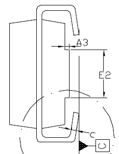 The 3D STEP model requires a minimum of 0.60 mm between the "D" and "D1" dimension. Otherwise, the 3D STEP model comes out corrupted. Any other Molded Body package would require a new component family in the calculator. We recommended that you use the mfr. recommended pattern and FP Designer for all your non-standard footprints. ------------- Stay connected - follow us! https://twitter.com/PCBLibraries" rel="nofollow - X - http://www.linkedin.com/company/pcb-libraries-inc-/" rel="nofollow - LinkedIn |