2 Pad Chips With Different Lead Length
Printed From: PCB Libraries Forum
Category: Libraries
Forum Name: Footprints / Land Patterns
Forum Description: [General or a CAD specific issues / discussions]
URL: https://www.PCBLibraries.com/forum/forum_posts.asp?TID=1988
Printed Date: 26 Jun 2026 at 2:51pm
Topic: 2 Pad Chips With Different Lead Length
Posted By: goaaron
Subject: 2 Pad Chips With Different Lead Length
Date Posted: 31 Oct 2016 at 6:12pm
|
Per IPC 7351B I am able to reproduce the PcbLibrary Expert footprint calculations when smt components have leads with the same length. However, I am unable to do the same with components that have different lead lengths. I.E. the "T" value in the drawing below are different and have different tolerances on either side of the component: 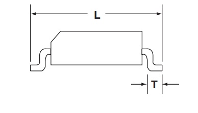 I'm following the calculations in IPC-7351B and am unable to reproduce the calculated Gref value nor the correct length for the two pads. IPC derives the interior separation between pads with the equation:  I've tried swapping out the all references to 2* Tmax with the sum of T1Max/T2max (the same for 2 Tmin) and Ttol with (T1max + T2max - T1max -T2max), but can't reproduce the calculator's results. Could someone clarify how it is done?
|
Replies:
Posted By: Tom H
Date Posted: 31 Oct 2016 at 7:00pm
|
You need to download the IPC-7351 Reference Calculator - http://www.pcblibraries.com/downloads" rel="nofollow - https://www.pcblibraries.com/downloads The Excel spreadsheet will explain the IPC-7351 mathematical model which includes the Package, Lead, Assembly, and Fabrication tolerances prior to adding the Toe, Heel and Side solder joint goals. Or if you have LE Pro, it's in this folder on your computer - C:\Program Files (x86)\PCB Libraries\Library Expert 2016\Documents ------------- Stay connected - follow us! https://twitter.com/PCBLibraries" rel="nofollow - X - http://www.linkedin.com/company/pcb-libraries-inc-/" rel="nofollow - LinkedIn |