IDF Export from Mentor Pads
Printed From: PCB Libraries Forum
Category: PCB Footprint Expert
Forum Name: Questions & Answers
Forum Description: issues and technical support
URL: https://www.PCBLibraries.com/forum/forum_posts.asp?TID=1876
Printed Date: 10 Oct 2025 at 4:44am
Topic: IDF Export from Mentor Pads
Posted By: David Baldwin
Subject: IDF Export from Mentor Pads
Date Posted: 18 Apr 2016 at 12:08pm
|
I created 2 new components with FPE. The 3D outline is on L25 as it should be. Whenever I export an IDF, the outlines are large and are not using L25 outline. This only happened with the 2 new parts that I just created using the latest version of FPE, everything else is okay. I deleted the terminals that FPE created on L25. Not sure why we would want terminals on L25, I thought we just needed a single closed polygon. I've submitted a SR to Mentor, but does anyone have any ideas on this? Thanks, Dave
|
Replies:
Posted By: Tom H
Date Posted: 18 Apr 2016 at 12:20pm
|
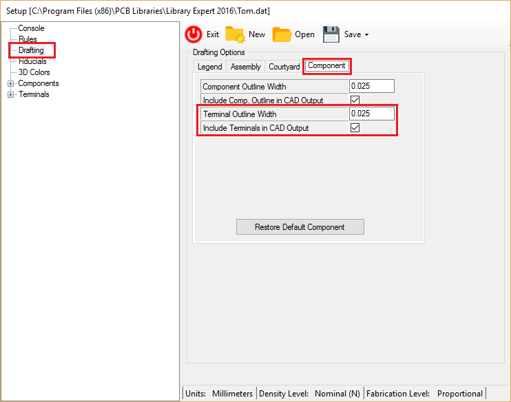
The Library Expert user determines all the CAD tool output parameters. To control the "Terminals" select "Preferences > Drafting > Component"  The new PADS VX imports 3D STEP models and the Layer_25 IDF export is being phased out. PCB Libraries, Inc. now gives the PADS interface away for free with the purchase of 3D STEP. ------------- Stay connected - follow us! https://twitter.com/PCBLibraries" rel="nofollow - X - http://www.linkedin.com/company/pcb-libraries-inc-/" rel="nofollow - LinkedIn |
Posted By: David Baldwin
Date Posted: 18 Apr 2016 at 12:45pm
|
I did find that option and I deselected it. But again, not sure why it is there and why advantage it provides. The mechanical engineer requested the IDF due to file size and other reasons. I sent the engineer a STEP file and he wants IDF, but the two new components I created are coming in too large as if it's using the pick box. PADS output report says it found the shape on L25, but it's not correct. Dave
|
Posted By: Tom H
Date Posted: 18 Apr 2016 at 12:55pm
|
Companies spend thousands $$$ on Valor VPL which superimposes the component footprint with the Land Pattern. The component footprint is the package and terminal outlines. There is a Footprint tab on every calculator to allow the user to insert the mfr. recommended pattern. If you enter the mfr. recommended footprint and the terminals fall off the pads, we probably would not recommend the mfr. pattern unless they make a statement that it is necessary to do so. If you have a single sided placement you can use Layer_25 to produce an assembly drawing that shows component and terminal outlines. Customers asked for this feature and we added it. It's up to you what to do with it or turn it off. ------------- Stay connected - follow us! https://twitter.com/PCBLibraries" rel="nofollow - X - http://www.linkedin.com/company/pcb-libraries-inc-/" rel="nofollow - LinkedIn |