Dimensional Principles of IPC-7351B
Printed From: PCB Libraries Forum
Category: PCB Footprint Expert
Forum Name: Questions & Answers
Forum Description: issues and technical support
URL: https://www.PCBLibraries.com/forum/forum_posts.asp?TID=1744
Printed Date: 19 Dec 2025 at 1:47pm
Topic: Dimensional Principles of IPC-7351B
Posted By: drj-bbe
Subject: Dimensional Principles of IPC-7351B
Date Posted: 04 Aug 2015 at 1:25am
|
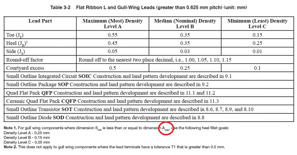
Hello Tom, There is a dimension "Amax" indicated in below principles of IPC-7351B, see below picture. But it seems there is no drawing to define which size is for "Amax". Could you please help on this question? Thanks
 |
Replies:
Posted By: Tom H
Date Posted: 04 Aug 2015 at 6:08am
This condition creates a Outward L lead - 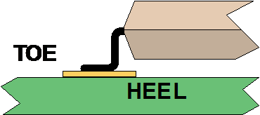 This lead style has a different calculation then the normal Gull Wing lead style: 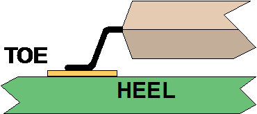 ------------- Stay connected - follow us! https://twitter.com/PCBLibraries" rel="nofollow - X - http://www.linkedin.com/company/pcb-libraries-inc-/" rel="nofollow - LinkedIn |
Posted By: drj-bbe
Date Posted: 04 Aug 2015 at 6:38pm
|
I have mark Amax and Smin below, is it correct? |
Posted By: Tom H
Date Posted: 04 Aug 2015 at 7:52pm
|
Please download the SMD Reference Calculator. All values and dimensional assignments are displayed. You can change the calculation values and observe the resulting land pattern results. Download here - http://www.pcblibraries.com/forum/ipc7351-smd-pth-reference-calculators_topic785.html" rel="nofollow - http://www.pcblibraries.com/forum/ipc7351-smd-pth-reference-calculators_topic785.html ------------- Stay connected - follow us! https://twitter.com/PCBLibraries" rel="nofollow - X - http://www.linkedin.com/company/pcb-libraries-inc-/" rel="nofollow - LinkedIn |
Posted By: drj-bbe
Date Posted: 04 Aug 2015 at 8:11pm
|
I cann't find dimension "A" mentioned above in SMD reference calculator. It seems only for chip component.
Could you tell me which size is for the dimension "A" ?
Thanks.
|
Posted By: Tom H
Date Posted: 05 Aug 2015 at 8:27pm
|
Sorry for the late reply especially for such a simple question, it's been really busy lately. Amax = the Lead Span 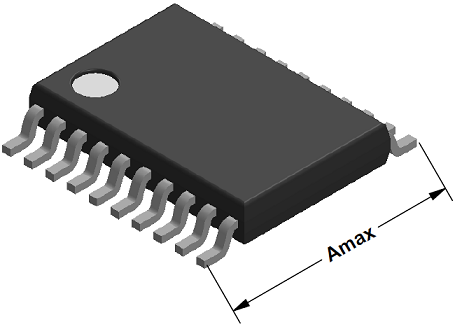 3D model created by Library Expert. ------------- Stay connected - follow us! https://twitter.com/PCBLibraries" rel="nofollow - X - http://www.linkedin.com/company/pcb-libraries-inc-/" rel="nofollow - LinkedIn |
Posted By: Tom H
Date Posted: 05 Aug 2015 at 8:57pm
|
This picture illustrates what the IPC-7351B text condition for Gull Wing lead is referring to. When the Terminal Leads bend inward. 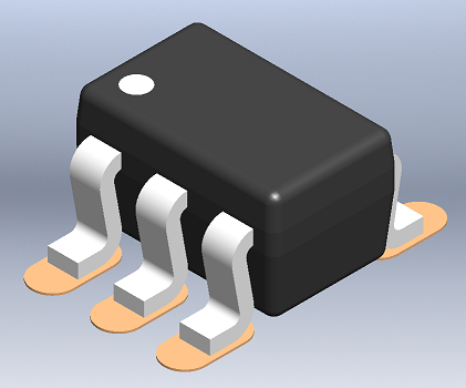 ------------- Stay connected - follow us! https://twitter.com/PCBLibraries" rel="nofollow - X - http://www.linkedin.com/company/pcb-libraries-inc-/" rel="nofollow - LinkedIn |
Posted By: KoryJohnsonTek
Date Posted: 06 Feb 2025 at 9:13am
|
Hi Tom. I realize this thread is 10 years old, but we are just now looking at this from the IPC standard perspective and were trying to understand Amax and what it means. After reading this thread, we are still confused. Are you still saying that Amax is the maximum lead expansion that IPC calls out in their calculations? It seems contrary to what we are see in the IPC formulas. How does your Amax have anything to do with whether the leads are bent inward? drj-bbe made a good point that it would seem to be related to what they showed, which you insisted it is not the case, given your second-to-last image. If the calculations are only about lead expansion and minimum lead length, it would seem that any calculation would always follow the exception in note 1.
|
Posted By: Tom H
Date Posted: 06 Feb 2025 at 9:23am
|
This thread explains the difference between the Gullwing and Outward L-Bend terminal leads of SOT packages. The image that illustrates the A-Max going to the Gullwing Knee was wrong. A-Max is the dimension from Toe to Toe, (not Knee to Knee). 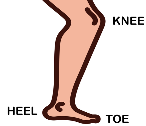 ------------- Stay connected - follow us! https://twitter.com/PCBLibraries" rel="nofollow - X - http://www.linkedin.com/company/pcb-libraries-inc-/" rel="nofollow - LinkedIn |
Posted By: KoryJohnsonTek
Date Posted: 06 Feb 2025 at 1:32pm
| Respectfully, I would like you to rethink the original poster's question. According to the IPC's note 1, an SOx part will usually always follow Note 1, and not the standard goal if Amax is the max lead expansion. Smin is calculated (in simple terms) as Lmin-(2*Tmax), and that is always going to be less that Amax - by your definition. What is it that we are missing? We understand what you are trying to say, but it seems like there is something missing somewhere, because you seem very sure of it, and we are very sure of the opposite. I really think that the poster's comment about this being the knee-to-knee dimension is correct, and it follows what you showed 05 Aug 2015 at 8:57pm. |
Posted By: Tom H
Date Posted: 06 Feb 2025 at 3:59pm
|
Here is the original drawing from 20 years ago when we were helping IPC define the difference between Gullwing and Outward L-Bend (Mini Gullwing) terminal leads. ------------- Stay connected - follow us! https://twitter.com/PCBLibraries" rel="nofollow - X - http://www.linkedin.com/company/pcb-libraries-inc-/" rel="nofollow - LinkedIn |
Posted By: KoryJohnsonTek
Date Posted: 14 Feb 2025 at 11:14am
|
Hi Tom. That was what our findings were/are. When you mentioned the knee, we were not seeing any reference in any of our datasheets for what the represents. Maybe it was just a matter of us misunderstanding your intent, I guess. Your Amax is in agreement with our Amax, which is the same as what IPC stated to me in a follow-up email. Thank you for your follow-through and patience!
|