

|
|
Molded Body D1 Dimension |
Post Reply 
|
| Author | |
kmorris 
Committee 
Joined: 15 Oct 2012 Location: United States Status: Offline Points: 14 |
 Post Options Post Options
 Thanks(1) Thanks(1)
 Quote Reply Quote Reply
 Topic: Molded Body D1 Dimension Topic: Molded Body D1 DimensionPosted: 07 Dec 2017 at 4:52pm |
|
In version 2017.17 the D1 dimension was added for molded body parts. Only problem is most vendors for for molded body capacitors do not specify that dimension in their datasheets. What is supposed to be done when that information is not specified?
Below are some examples: |
|
 |
|

|
|
|
|
|
Tom H
Admin Group 

Joined: 05 Jan 2012 Location: San Diego, CA Status: Online Points: 6083 |
Post Options
Thanks(0)
Quote Reply
Posted: 07 Dec 2017 at 5:05pm |
|
We had to add the D1 dimension due to new mico-miniature Molded Body packages and to accurately create the 3D STEP model.
The D1 dimension is a minimum 0.40 mm smaller than the D dimension. It depends on the package size. A good check would be to locate a similar size Molded Body Capacitor (CAPPM) or Diode (DIOM) in the SM FPX file and use the same reduction. A package that is 7.30 mm long could have a D1 dimension that is between 0.60 mm and 0.80 mm smaller for D1. I noticed you are on V2017.17, but the latest release is V2017.20 (which is much more stable and bug free). V2017.21 comes out next week. If you need to upgrade, let us know. |
|
|
|
|
kmorris
Committee
Joined: 15 Oct 2012 Location: United States Status: Offline Points: 14 |
Post Options
Thanks(0)
Quote Reply
Posted: 07 Dec 2017 at 5:16pm |
|
Using the latest version just did not notice this change until today. Guess the engineers I am working with have not used a new molded body part in a while. I'll do as you recommend.
|
|
|
|
|
AA310
New User 
Joined: 13 Jan 2026 Status: Offline Points: 1 |
Post Options
Thanks(0)
Quote Reply
Posted: 4 hours 3 minutes ago at 8:19am |
|
Hello hello,
I am running the 26.07 version and the expected D1 reduction for a D case tantalum cap (EIA 7343–31) is 0.6 mm which I find ridiculous. I've measured most capacitors that we use in our designs (since the datasheets do not mention this parameter) and their D1 is at a minimum 7 mm.
Is there any way around this? I would like the footprints to be as accurate as possible. Thank you for your support! |
|
|
|
|
Tom H
Admin Group
Joined: 05 Jan 2012 Location: San Diego, CA Status: Online Points: 6083 |
Post Options
Thanks(1)
Quote Reply
Posted: 3 hours 42 minutes ago at 8:40am |
|
The Molded Body component family in the IPC-7351/7352 is intended for the JEDEC DO-241 (SMA, SMB & SMC) where the terminal lead is 0.20 mm thick and requires 0.60 mm difference between the 'D' and 'D1' dimensions.
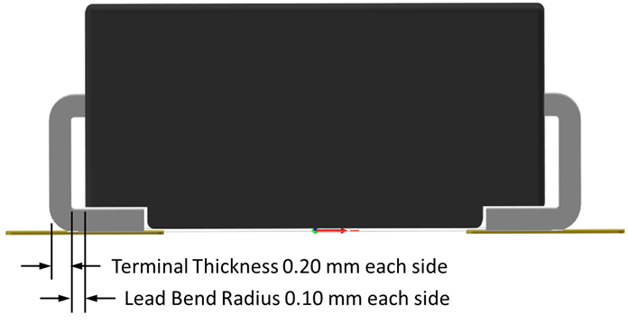 The EIA 7343–31 has the terminal leads flat against the component package body. Use FP Designer and the mfr. recommended pattern to create these footprints. |
|
|
|
|
Tom H
Admin Group
Joined: 05 Jan 2012 Location: San Diego, CA Status: Online Points: 6083 |
Post Options
Thanks(0)
Quote Reply
Posted: 7 minutes ago at 12:15pm |
|
The main issue with the Molded Body terminal lead flat against the package body is the 3D Model.
We'll add a new component family for the EIA 7343 series but the 3D STEP model will be an Extruded Block (no terminal leads). This condition will take place when 'D1' is less than 0.60 mm than 'D'. The program will throw a warning. It will be in the next V26.08 pre-release next week. Thanks |
|
|
|
|
Post Reply
|
|
| Tweet |
| Forum Jump | Forum Permissions You cannot post new topics in this forum You cannot reply to topics in this forum You cannot delete your posts in this forum You cannot edit your posts in this forum You cannot create polls in this forum You cannot vote in polls in this forum |


 Topic Options