
 |

|
The '+' Polarity Symbol Dimensions |
Post Reply 
|
| Author | |
m.elsayed 
Advanced User 
Joined: 22 Sep 2016 Status: Offline Points: 72 |
 Post Options Post Options
 Thanks(0) Thanks(0)
 Quote Quote  Reply Reply
 Topic: The '+' Polarity Symbol Dimensions Topic: The '+' Polarity Symbol DimensionsPosted: Yesterday at 6:58am |
|
I have '+' polarity marker in Silkscreen and Assembly layers with same dimension as line width = 0.05 mm and size = 1.016 mm
However, when open in Altium Designer the '+' symbol has different dimension values. Footprint Expert:  Altium:   |
|
 |
|

|
|
 |
|
Jeff.M 
Admin Group 

Joined: 16 May 2012 Location: San Diego Status: Offline Points: 484 |
 Post Options Post Options
 Thanks(0) Thanks(0)
 Quote Quote  Reply Reply
 Posted: Yesterday at 10:47am Posted: Yesterday at 10:47am |
|
Please provide an fpx library file with a sample part so we can try to reproduce your problem. You can send it to Jeff.
|
|
 |
|
m.elsayed 
Advanced User 
Joined: 22 Sep 2016 Status: Offline Points: 72 |
 Post Options Post Options
 Thanks(0) Thanks(0)
 Quote Quote  Reply Reply
 Posted: Yesterday at 1:44pm Posted: Yesterday at 1:44pm |
|
TE_Connectivity_2025-09-14_13-44-19.fpx
please check
|
|
 |
|
tgrodnicki 
Advanced User 
Joined: 30 Sep 2014 Status: Offline Points: 128 |
 Post Options Post Options
 Thanks(1) Thanks(1)
 Quote Quote  Reply Reply
 Posted: 18 hours 17 minutes ago at 11:22pm Posted: 18 hours 17 minutes ago at 11:22pm |
|
Footprint Expert reports the length of the lines forming the cross as the maximum value. Most CAD programs do not account for round ends when reporting the length of the lines. If you subtract the width (0.050) from the length reported by Footprint Expert (1.016), you get the result reported by Altium Designer (0.966).
|
|
 |
|
m.elsayed 
Advanced User 
Joined: 22 Sep 2016 Status: Offline Points: 72 |
 Post Options Post Options
 Thanks(0) Thanks(0)
 Quote Quote  Reply Reply
 Posted: 11 hours 48 minutes ago at 5:51am Posted: 11 hours 48 minutes ago at 5:51am |
|
but also i found in line width changed to 0.254 other layer assembly
however i changed to 0.05
|
|
 |
|
Tom H 
Admin Group 

Joined: 05 Jan 2012 Location: San Diego, CA Status: Offline Points: 5865 |
 Post Options Post Options
 Thanks(0) Thanks(0)
 Quote Quote  Reply Reply
 Posted: 2 hours 14 minutes ago at 3:25pm Posted: 2 hours 14 minutes ago at 3:25pm |
|
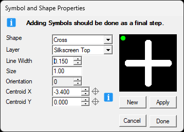
I created a Silkscreen Plus + symbol in Footprint Expert 1.00 mm X 0.15 mm line width.
Here is the Footprint Expert Symbol dialog box:  I translated the footprint to Altium and here are the Plus Symbol dimensions.  Here is the Altium Properties for the Polarity Marker:  It seems to be working 100% correct. Can you confirm that the issue you reported is working correctly? |
|
 |
|
Post Reply 
|
|
| Tweet |
| Forum Jump | Forum Permissions  You cannot post new topics in this forum You cannot reply to topics in this forum You cannot delete your posts in this forum You cannot edit your posts in this forum You cannot create polls in this forum You cannot vote in polls in this forum |