

|
|
Pin 1 definition Vs Tape&Reel format |
Post Reply 
|
| Author | |
Nightwish 
Active User 

Joined: 20 Feb 2012 Location: Shanghai China Status: Offline Points: 33 |
 Post Options Post Options
") Thanks(0) Thanks(0)
 Quote Reply Quote Reply
 Topic: Pin 1 definition Vs Tape&Reel format Topic: Pin 1 definition Vs Tape&Reel formatPosted: 16 May 2013 at 10:39pm |
|
These days I created a cell for a connector and the Pin 1 is set on lowwer left while our DFME set the pin 1 on top in his VPL library. I am not sure if IPC has this kind of definition on how to define pin 1 according to component package in tape&reel? Picture below shows the snap shot of the tape&reel format. 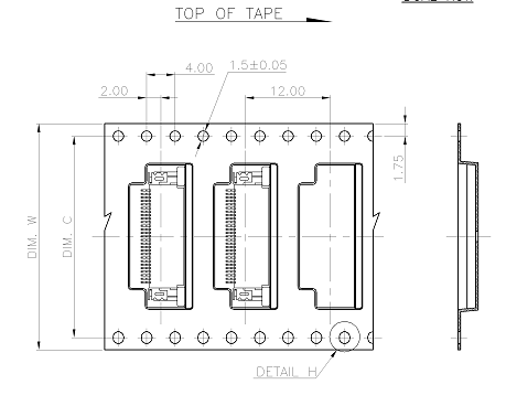 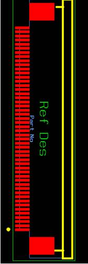 Cell CellThanks,
Nightwish
|
|
 |
|
|
|
|
Tom H
Admin Group 

Joined: 05 Jan 2012 Location: San Diego, CA Status: Offline Points: 5716 |
Post Options
Thanks(0)
Quote Reply
Posted: 17 May 2013 at 6:21am |
|
The PCB Footprint Expert (FPX) allows you to output every library part in any rotation you want.
On Monday, IPC will submit a Press Release to all news publications that they are now shipping FPX Lite with the purchase of the IPC-7351 Land Pattern standard. |
|
|
|
|
Nightwish
Active User
Joined: 20 Feb 2012 Location: Shanghai China Status: Offline Points: 33 |
Post Options
Thanks(0)
Quote Reply
Posted: 19 May 2013 at 11:05pm |
|
Hi Tom,
Thanks for your reply on this. I know we can easily rotate cell when creating it but I want to know if the zero rotation of land pattern has something to do with the package type in tape & reel. In Footprint Expert the default Orientation Pin 1 for TO part is down and for SOP it is left, is this an IPC standard?
Thanks,
Nightwish
|
|
|
|
|
Tom H
Admin Group
Joined: 05 Jan 2012 Location: San Diego, CA Status: Offline Points: 5716 |
Post Options
Thanks(0)
Quote Reply
Posted: 20 May 2013 at 6:48am |
|
There is a standard that you can search for EIA-481-D-2008m however the biggest problem is that only a small number of component manufacturer's use it. IPC and PCB Libraries, Inc. did research on this for the IPC-7351A and discovered that even the same component manufacturer breaks the Zero Component Orientation rules. So IPC established their own Zero Component Orientation (ZCO) for Footprint library parts. Then is 2007 IEC released their own Zero Component Orientation which was rotated 90 degrees from IPC. I explain EIA, IPC and IEC ZCO in this presentation - PCB Design Optimization Starts in the CAD Library available here - http://www.pcblibraries.com/forum/pcb-design-optimization-starts-in-the-cad-library_topic468.html
EIA-481-D - 8 mm THROUGH 200 mm EMBOSSED CARRIER TAPING AND 8 mm & 12 mm PUNCHED CARRIER TAPING OF SURFACE MOUNT COMPONENTS FOR AUTOMATIC HANDLING. |
|
|
|
|
Post Reply
|
|
| Tweet |
| Forum Jump | Forum Permissions You cannot post new topics in this forum You cannot reply to topics in this forum You cannot delete your posts in this forum You cannot edit your posts in this forum You cannot create polls in this forum You cannot vote in polls in this forum |


 Topic Options